In This Episode
Video Transcript
[Frankie] You're watching Powernation!
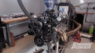
[Pat] Today in Engine Power we embark on a high powered LS adventure with Summit Racing's new robust Pro LS block and Trick Flow induction that flows like Niagara Falls. [Frankie] This will be a 427 cubic inch street machine and we'll show you how we prep and machine this ground up build and then start clicking it together. [ Music ]
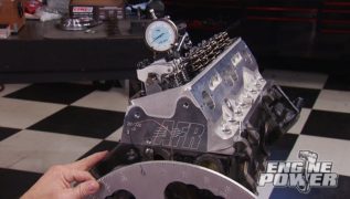
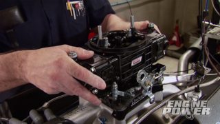
It's always like Christmas in the summer time when you get to unbox a bunch of parts and start a brand new engine build, and that's exactly what we're doing today in Engine Power. [Pat] A big part of how an engine runs is the sum of its parts. So today we're gonna use some parts that were specifically designed for the LS platform by the folks at Summit Racing Equipment. This is from Summit's Pro LS line. They went the extra mile and developed parts for engines from mild to the extremely wild, and we have a great selection here for our engine. We're gonna be building a 427 inch LS based engine. We've got some really cool things that go with that. It all starts out with their 4340 forged four inch crankshaft. This is their Pro LS with a 58 tooth reluctor. Moving on to the connecting rod. This is a 6-125 length, 927 pin, 2-100 big end. Their Pro LS piston is a nice piece. 4-125 bore, 26-18 material, 110 compression height. They also make their own dampers. This is a damper that is SFI certified. So if you go to the track you are good to go. Going along with all this other good stuff are their camshafts, their Pro LS camshafts. Very specific profiles with lobes that will do anything that you want from mild naturally aspirated to big boosted applications. That camshaft ties in with big air flow and we have that covered with Trick Flow's new 280cc LS-3 style cylinder head. These are pretty special because they have been set up for big boost. We can use them naturally aspirated as well but they have a lot of great features. 67cc fully cnc'ed chamber. 2-165 severe duty intake valve, Inconel 1-600 exhaust. So if you want to use these on a big boost application you are all set. It has a titanium retainer with a double spring. Now you can say these heads are pretty hip because that is the process of the casting that makes it stronger and more stable. Hot isostatic pressed. That means these heads will stay very stable under high pressure and they are 2750 thousandths thick to make sure all of that boost or whatever you're doing stays inside the combustion chamber. To pair with our cylinder heads we have Trick Flow's newest RSeries fuel injection intake that is throttle body based. So it looks like an old school hot rod. We have a lot of other cool parts like the FiTech injection and other things but we have to have a good foundation to put all of these parts in and Frankie's gonna tell you about that. [Frankie] For the base of this build we could use an OE block but for the displacement that we're gonna be running this is something that's much easier to get and actually way better. This is the newest offering from Summit Racing's SPC Street Performance Competition engine block line, their Pro LS engine block. Now this is a brand new casting. This is cast in new molds in a top tier OE foundry in Germany and then it's brought over to the USA and fully machined except for the cylinder bores. They leave those unfinished that way you can set them up for your application as far as your piston to wall clearance, cross hatch angle, and surface profile but they have everything else machined. That way they can keep you out of machine shop jail as they call it and you can build this engine at home. So it has a ton of cool features. So we'll just go through them. It has an unfinished 4-125 bore but you can take it out to 4-185 if you want. It has casting clearance for our four inch stroke but with a little bit of hand clearancing or machine shop clearancing you can get it up to 4-250 inch stroke. It has a reinforced exit. They've added material and it's about three quarter inch thick. The decks are a six bolt design like our cylinder heads. That way you have some extra clamp force to help seal up those big boosted engines with a lot of cylinder pressure. They have also extended the cylinder bores about a quarter inch for extra skirt support on those stroker applications. It does have priority main oiling. It also has threaded oil gallery plugs and they do that for a very specific reason. The lifter crossover is actually in the center and they plug these mechanically with pipe plugs. That way if you're doing a race application with a lot of oil pressure you don't have to worry about the cam retaining plate flexing and possibly leaking. It has all the other same architecture as a conventional LS. It actually blends a little bit of the Gen-3 and Gen-4. So it does use a front cam sensor and a conventional crank sensor but it will take a tie-bar LS lifter. It will take a conventional LS lifter, and a lot of the other parts interchange. This is pretty much ready to go. All we're gonna do to it is go through our normal block prep, deburring, oil porting, stuff like that. Then we just have to finish the cylinder bores and it will be ready for final cleaning and assembly. [Pat] Coming up, we kick off the build by giving our Summit block extra slick attention and it hits the hone for a torque plate date.
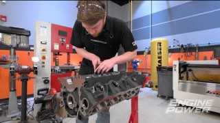
[Frankie] We have our Summit Pro LS block out of the assembly area into our dirty area over here by our machines. Like we said, the first thing we're gonna do is do all of our block prep. We're gonna deburr the block and do some light porting on the oil passageways. This is something you've seen us do a bunch and we feel is extremely important on a fresh build like this. We do this to stock castings and aftermarket castings. Although an aftermarket casting is generally much better and the casting is much smoother, usually there's also a lot more machined surfaces because the manufacturers pay a little bit more attention to all the areas of the block that they want to machine. So we want to go through and break all those sharp edges. This not only makes the block easier to work with but also helps prevent stress risers, which could turn into cracks, and then we're gonna go through and port some of the oil passageways to help improve oil flow. The great thing about this is yes, it does take quite a bit of time but once it's done it's done on the block for life. So barring you junking a block this is something that will be done. Whether you're rebuilding the engine, running it forever, it is an investment of time into your engine. So we're gonna get a grinder and then we'll get started. We have a selection of different carbide bits to choose from and we'll start with a tapered ferrous bit. Sharp edges are created during the machining process and we simply want to break that edge or round it off. We are not trying to put a huge bevel on it or remove a lot of material. So a light touch is really all that's needed with a sharp carbide burr. You also have to be careful around the critical machined areas like the decks, cam tunnel, and mains so that you don't accidentally slip and put a big gouge in your fresh block. Just remember, this is a process that can take a while if you're going over the whole block, and you can double check and make sure you don't miss any areas by running your hands over the entire piece. [Pat] Next Frankie will work on the oil galleries, which mainly involve rounding sharp edges and corners that cause oil to eddy and restrict flow. [ grinder humming ] It can take a couple of different burrs but you can see that the finished product is much smoother and removes those sharp edges like we mentioned. We'll follow the galleries all the way to the mains where an air pencil and an eighth inch carbide are used to round off the main passageways. These are drilled to feed oil to the main bearings and that leaves sharp edges as well. So we can carefully smooth those out. Once the block is cleaned of all the grinding material and dust we can load it into our cylinder hone for the next stage of the machining process. With the engine block all slicked up now it's time to set the bores to final size. We have it in our Sunnen SV-15 hone and we are ready to go. Next thing we're gonna do is put a torque plate on before we get honing. That means we're gonna take the gasket that we're gonna use and the fasteners that we're gonna use when we use a torque plate, and for that we picked up an ARP head stud kit. Now this is specifically for the LSX because remember this is a six bolt head. It comes with everything that we need to bolt it down. These are all made out of ARP 2000 material. Great tensile strength, great longevity, and they even come with their ARP specifically engineered Ultra Torque Lube so you get accurate torque figures and maximum clamp load. One thing of note. The washers have a serrated side on them. Now that is very important because you've heard us talk about this before. If you put lube on both sides of that washer when it is assembled it can act like a bearing and potentially give you an inaccurate and heavier torque value and potentially ruin your fastener. So these have been made with a serration on one side and that goes down on the cylinder head side. Perhaps the most important thing in this kit is the instructions. ARP puts a very concise set of instructions in every kit. Remember these are not torque to yield. If you follow these to the "T" you'll get the maximum benefit and maximum results from these studs. The next thing we're gonna do is get the gasket that we're gonna use and we're gonna get our ICT billet plate on and get it torqued downed. We are using the exact head gasket as will be used in the build and it is clamped down by the six bolt ICT billet LS torque plate. The ARP studs are screwed into the block hand tight and the washers are dropped on. ARP Ultra Torque Lube is applied to the threads and the tops of the washers before it is followed by the 12 point nuts. Following ARP's instructions the head studs are torqued in sequence with the 11 millimeter studs going to 90 pound feet in three stages and the eight millimeter studs being tightened to 28 pound feet. [Frankie] Once Pat gets the hone set up for our application he's gonna use our 150 grit diamond abrasives to remove the minor five thousandths of an inch needed to set our bores to the correct size for our piston to wall clearance. This is also enough to remove the cylinder wall distortion that the torque plate duplicates to achieve a round cylinder and set the valley in the surface profile of this plateau hone. Once each cylinder is roughed out to size we will trade the coarse 150 grit abrasives for a finer set of 600 grit diamonds that will effectively knock the peaks off the cylinder wall finish. [ Music ] [ hone machine humming ] After five strokes at a lighter load we will clean the cylinders and use our profilometer and TraceBoss software from Total Seal Piston Rings to measure our surface finish. For this N/A street application this result is perfect and will give us a well sealed cylinder with a long lifespan. [Pat] Long! [Frankie] Up next, it's all about tolerance as we dial in crank balance and set bearing clearances.
[Frankie] Okay, I think that is everything we need. We are getting set up to balance our crankshaft. That's the next thing we're gonna do in the process of building this 427. So we have everything laid out that we're going to need. What we're gonna do is get our crank set on the machine and then we'll start measuring and get some weights. After getting the crank set up in the machine we can start measuring the weights of each of the components in the rotating assembly. So we need to measure both the rotating and reciprocating pieces and they entered into the system in grams. [Pat] Since the scale is connected to the CWT software all we have to do is lay each component on it and hit the print button to send it to the bob weight sheet. Even the wrist pin locks are measured, and once we have our target bob weight, 1,818 grams in this case, we can assemble one for each crank pin and install them with the CWT centering device. [ Music ]
We'll begin with spinning the crank at 500 rpm to see where we're starting. [ Music ] [Frankie] Okay! That's actually extremely good. We are at .114 ounce inch on the front. Basically we are not gonna touch front. On the back we're extremely close, 1.495 ounce inch. A little over 12 grams right here on the counterweight. That is something we can take care of with a small hole. We're gonna do that and get this thing dialed in real quick. We are all set up to drill our hole in our rear counterweight. We're gonna step this up with drill sizes but something to think about is you do not want to do this dry. This is a hardened crank. You need some kind of lubrication. If you notice we have cans of this stuff, Seafoam's Deep Creep, all over the shop because it's good for everything. It's like an adjustable wrench in a can. You guys have probably seen it for breaking bolts loose. Use it as a penetrating oil for stuck fasteners or something like that but it's also good for a bunch of other stuff. We use it to clean machines, clean engines, make'em look glossy and new. It also works really good as a rust preventative. So we'll use it on blocks and parts when they're coming out of the cleaner, and it works really good as a machining fluid. Works really good if we're cutting something on the lathe or mill or if we're drilling because it not only has lubricity but it also resists heat and evaporation. It's got a nice straw and it comes out in a nice foam. That way you don't make a mess. You can get a little bit on there and we're ready to go. We use a quarter inch drill to make a starter hole since it is much easier to make sure the hole is centered on the 800 thousandths wide counterweight than a larger piece. Once we have a decent hole we can change out to a nine-sixteenths hyper step drill and slowly remove the material, checking the crank as we go at 750 rpm until we get it where we want for imbalance. [ Music ]
Alright, there we go. We are well under our tolerance and we are 176 degrees apart. We are at .144 ounce inch on the rear, .145 on the right. So we're gonna go ahead and save that as our last spin and our forces on the center of the crank are minimized down to .013 ounce inch. If we look at our before and after here just at 6,000 rpm on the rear we're going from 95 pounds of force down to just 9.2. So that is very good. We're gonna get this crank off of here. Get it cleaned up and then we can start moving even closer to assembly. [ hammer tapping ] [Pat] With everything cleaned up we're gonna start measuring our main and rod bearing clearances. With coated Summit bearings in the block and main caps there are gently tapped down and then these 180,000 psi main bolts are installed and snugged down with oil on the threads. We'll install only the three rear caps. So now we can fit our dial bore gauge in for measuring. These are reusable fasteners but have a torque to angle spec. So they are torqued initially to 15 pound feet before the inners are tightened to 80 degrees more and then the outers are 51 degrees more. The side bolts are tightened to 18 pound feet and then a dial bore gauge set to the respective main journal size is used to measure the oil clearances and they fall between 23 and 25 ten thousandths. [Frankie] Next we can check the rod clearances, first bracing them in our ARP rod vice. The ARP 2000 bolts are torqued to 88 pound feet with ARP lube to achieve the proper stretch, which is from 51 to 55 ten thousandths, and then a two to three inch micrometer is set to the matching journal size. It is used to zero out the dial bore gauge and then we can take a direct oil clearance measurement. All of the rods are between the tight tolerance of 20 to 21 ten thousandths, which is right where we want them. We are coming along really nicely. All of our tolerances are landing within one or two ten thousandths of an inch. So that really tells you these parts have a very tight tolerance on machining. So we're looking really good and when we come back we're gonna be moving on and getting this thing into assembly. [ Music ] [Pat] Coming up, we get our pistons and rods installed so we can get this 427 making some horsepower.
[Frankie] We are getting close to assembly but there's one last thing we need to do for our 427 before we can actually start putting parts together and getting them inside our engine and that is file the end gaps for our rings. Now for this build we're gonna be using a set of Total Seal's TFX rings. This is a line they created because they are a huge proponents of using thinner ring packs in any engine. So for our build we're gonna be using a 1.2, 1.2, 3mm set that matches our pistons. These are a 440-B stainless top with their C-56 proprietary face coating, a 1.2 steel napier second ring, and then a standard tension oil control ring. There are a ton of huge benefits to running a thinner ring pack like this. A thinner ring like the TFX set has a few distinct advantages over bulkier ring sets. The big difference is the reduced surface area and pressure of the ring face contacting the cylinder wall, which reduces the amount of friction between the cylinder wall and the ring immensely. This is also true for the oil control ring pack where a reduced thickness can lessen friction while still controlling oil properly. This not only frees up horsepower by reducing the force required to rotate the engine but also reduces the wear on the cylinder walls. Thinner rings also have better conformity to the piston and cylinder wall itself, which improves its SEALING on both and a better sealed cylinder is like catching free horsepower. We are using our Summit Pro ring filer to set the ring gaps following Total Seal's recommendations. We like to err on the safer side. So we're setting the gaps at 23 thousandths on the top and 25 thousandths on the second. We can precisely remove the material from the rings in one thousandths increments and then carefully deburr them with an abrasive stone. After squaring them in the bores an even, light drag on the feeler gauge tells us we are right on size. [Pat] Finally with everything cleaned we can start prepping the main bearings for assembly with Hot Shot's Secret assembly lube. This will provide protection for our four inch stroke Pro LS crank from assembly to the first start up. Each of the main caps are set in place and tapped into their registers with a rubber hammer to ensure they are fully seated. After pre-loading the crank in the forward position to align the thrust faces the internal main bolts are torqued in the same sequence as earlier from the inside out. 15 pound feet on all of them followed by 80 degrees rotation on the inners and 51 more degrees on the outers. Since the side bolts are exposed they receive some rtv underneath the head to prevent oil seepage before they are installed and torqued to 18 pound feet. [Frankie] The rod and piston assemblies can be assembled next. So the 6-125 long H-beams are set in the proper orientation with the heavy duty 927 wrist pins. The Pro LS pistons come with a thick single spiral lock which can be worked into place with your fingers and a small pocket screwdriver. Once they are all together we can start loading the 4-125 bore pistons with their ring sets. Because of their 1-110 compression height they use an oil support rail and the rings are installed from the bottom up. These pistons are a 26-18 alloy, have a 23cc dish, and deep valve reliefs. So combined with the beefy wrist pins and H-beams they can support quite a bit of power. [Pat] Each set are installed into the block with an ARP 4-125 fixed ring compressor, and with the thin TFX rings they can be installed by hand. The rods are guided onto the journals from the bottom and the caps are installed in the correct orientation and snugged down with an impact for now. This ensures the bearings are concentric while all the assemblies are installed and then the block can be flipped over to torque the rod bolts. They are tightened to 88 pound feet and each one is checked for the proper stretch again making sure they all land between 51 and 55 ten thousandths to achieve the proper clamp load for the fasteners. [Frankie] Feel pretty good about that. Once we get the bottom end into an engine that means we're making real progress and this is about as sturdy of a foundation as you can get. This will probably hold 1,000 horsepower if you need it to but today we're slim out of time. [Pat] When it comes back we're gonna put in the camshaft, cylinder heads, the valvetrain, induction, and get this ready to make big power on the dyno. It's gonna be pretty awesome. [Frankie] See you next time!
Show Full Transcript
[Pat] Today in Engine Power we embark on a high powered LS adventure with Summit Racing's new robust Pro LS block and Trick Flow induction that flows like Niagara Falls. [Frankie] This will be a 427 cubic inch street machine and we'll show you how we prep and machine this ground up build and then start clicking it together. [ Music ]
It's always like Christmas in the summer time when you get to unbox a bunch of parts and start a brand new engine build, and that's exactly what we're doing today in Engine Power. [Pat] A big part of how an engine runs is the sum of its parts. So today we're gonna use some parts that were specifically designed for the LS platform by the folks at Summit Racing Equipment. This is from Summit's Pro LS line. They went the extra mile and developed parts for engines from mild to the extremely wild, and we have a great selection here for our engine. We're gonna be building a 427 inch LS based engine. We've got some really cool things that go with that. It all starts out with their 4340 forged four inch crankshaft. This is their Pro LS with a 58 tooth reluctor. Moving on to the connecting rod. This is a 6-125 length, 927 pin, 2-100 big end. Their Pro LS piston is a nice piece. 4-125 bore, 26-18 material, 110 compression height. They also make their own dampers. This is a damper that is SFI certified. So if you go to the track you are good to go. Going along with all this other good stuff are their camshafts, their Pro LS camshafts. Very specific profiles with lobes that will do anything that you want from mild naturally aspirated to big boosted applications. That camshaft ties in with big air flow and we have that covered with Trick Flow's new 280cc LS-3 style cylinder head. These are pretty special because they have been set up for big boost. We can use them naturally aspirated as well but they have a lot of great features. 67cc fully cnc'ed chamber. 2-165 severe duty intake valve, Inconel 1-600 exhaust. So if you want to use these on a big boost application you are all set. It has a titanium retainer with a double spring. Now you can say these heads are pretty hip because that is the process of the casting that makes it stronger and more stable. Hot isostatic pressed. That means these heads will stay very stable under high pressure and they are 2750 thousandths thick to make sure all of that boost or whatever you're doing stays inside the combustion chamber. To pair with our cylinder heads we have Trick Flow's newest RSeries fuel injection intake that is throttle body based. So it looks like an old school hot rod. We have a lot of other cool parts like the FiTech injection and other things but we have to have a good foundation to put all of these parts in and Frankie's gonna tell you about that. [Frankie] For the base of this build we could use an OE block but for the displacement that we're gonna be running this is something that's much easier to get and actually way better. This is the newest offering from Summit Racing's SPC Street Performance Competition engine block line, their Pro LS engine block. Now this is a brand new casting. This is cast in new molds in a top tier OE foundry in Germany and then it's brought over to the USA and fully machined except for the cylinder bores. They leave those unfinished that way you can set them up for your application as far as your piston to wall clearance, cross hatch angle, and surface profile but they have everything else machined. That way they can keep you out of machine shop jail as they call it and you can build this engine at home. So it has a ton of cool features. So we'll just go through them. It has an unfinished 4-125 bore but you can take it out to 4-185 if you want. It has casting clearance for our four inch stroke but with a little bit of hand clearancing or machine shop clearancing you can get it up to 4-250 inch stroke. It has a reinforced exit. They've added material and it's about three quarter inch thick. The decks are a six bolt design like our cylinder heads. That way you have some extra clamp force to help seal up those big boosted engines with a lot of cylinder pressure. They have also extended the cylinder bores about a quarter inch for extra skirt support on those stroker applications. It does have priority main oiling. It also has threaded oil gallery plugs and they do that for a very specific reason. The lifter crossover is actually in the center and they plug these mechanically with pipe plugs. That way if you're doing a race application with a lot of oil pressure you don't have to worry about the cam retaining plate flexing and possibly leaking. It has all the other same architecture as a conventional LS. It actually blends a little bit of the Gen-3 and Gen-4. So it does use a front cam sensor and a conventional crank sensor but it will take a tie-bar LS lifter. It will take a conventional LS lifter, and a lot of the other parts interchange. This is pretty much ready to go. All we're gonna do to it is go through our normal block prep, deburring, oil porting, stuff like that. Then we just have to finish the cylinder bores and it will be ready for final cleaning and assembly. [Pat] Coming up, we kick off the build by giving our Summit block extra slick attention and it hits the hone for a torque plate date.
[Frankie] We have our Summit Pro LS block out of the assembly area into our dirty area over here by our machines. Like we said, the first thing we're gonna do is do all of our block prep. We're gonna deburr the block and do some light porting on the oil passageways. This is something you've seen us do a bunch and we feel is extremely important on a fresh build like this. We do this to stock castings and aftermarket castings. Although an aftermarket casting is generally much better and the casting is much smoother, usually there's also a lot more machined surfaces because the manufacturers pay a little bit more attention to all the areas of the block that they want to machine. So we want to go through and break all those sharp edges. This not only makes the block easier to work with but also helps prevent stress risers, which could turn into cracks, and then we're gonna go through and port some of the oil passageways to help improve oil flow. The great thing about this is yes, it does take quite a bit of time but once it's done it's done on the block for life. So barring you junking a block this is something that will be done. Whether you're rebuilding the engine, running it forever, it is an investment of time into your engine. So we're gonna get a grinder and then we'll get started. We have a selection of different carbide bits to choose from and we'll start with a tapered ferrous bit. Sharp edges are created during the machining process and we simply want to break that edge or round it off. We are not trying to put a huge bevel on it or remove a lot of material. So a light touch is really all that's needed with a sharp carbide burr. You also have to be careful around the critical machined areas like the decks, cam tunnel, and mains so that you don't accidentally slip and put a big gouge in your fresh block. Just remember, this is a process that can take a while if you're going over the whole block, and you can double check and make sure you don't miss any areas by running your hands over the entire piece. [Pat] Next Frankie will work on the oil galleries, which mainly involve rounding sharp edges and corners that cause oil to eddy and restrict flow. [ grinder humming ] It can take a couple of different burrs but you can see that the finished product is much smoother and removes those sharp edges like we mentioned. We'll follow the galleries all the way to the mains where an air pencil and an eighth inch carbide are used to round off the main passageways. These are drilled to feed oil to the main bearings and that leaves sharp edges as well. So we can carefully smooth those out. Once the block is cleaned of all the grinding material and dust we can load it into our cylinder hone for the next stage of the machining process. With the engine block all slicked up now it's time to set the bores to final size. We have it in our Sunnen SV-15 hone and we are ready to go. Next thing we're gonna do is put a torque plate on before we get honing. That means we're gonna take the gasket that we're gonna use and the fasteners that we're gonna use when we use a torque plate, and for that we picked up an ARP head stud kit. Now this is specifically for the LSX because remember this is a six bolt head. It comes with everything that we need to bolt it down. These are all made out of ARP 2000 material. Great tensile strength, great longevity, and they even come with their ARP specifically engineered Ultra Torque Lube so you get accurate torque figures and maximum clamp load. One thing of note. The washers have a serrated side on them. Now that is very important because you've heard us talk about this before. If you put lube on both sides of that washer when it is assembled it can act like a bearing and potentially give you an inaccurate and heavier torque value and potentially ruin your fastener. So these have been made with a serration on one side and that goes down on the cylinder head side. Perhaps the most important thing in this kit is the instructions. ARP puts a very concise set of instructions in every kit. Remember these are not torque to yield. If you follow these to the "T" you'll get the maximum benefit and maximum results from these studs. The next thing we're gonna do is get the gasket that we're gonna use and we're gonna get our ICT billet plate on and get it torqued downed. We are using the exact head gasket as will be used in the build and it is clamped down by the six bolt ICT billet LS torque plate. The ARP studs are screwed into the block hand tight and the washers are dropped on. ARP Ultra Torque Lube is applied to the threads and the tops of the washers before it is followed by the 12 point nuts. Following ARP's instructions the head studs are torqued in sequence with the 11 millimeter studs going to 90 pound feet in three stages and the eight millimeter studs being tightened to 28 pound feet. [Frankie] Once Pat gets the hone set up for our application he's gonna use our 150 grit diamond abrasives to remove the minor five thousandths of an inch needed to set our bores to the correct size for our piston to wall clearance. This is also enough to remove the cylinder wall distortion that the torque plate duplicates to achieve a round cylinder and set the valley in the surface profile of this plateau hone. Once each cylinder is roughed out to size we will trade the coarse 150 grit abrasives for a finer set of 600 grit diamonds that will effectively knock the peaks off the cylinder wall finish. [ Music ] [ hone machine humming ] After five strokes at a lighter load we will clean the cylinders and use our profilometer and TraceBoss software from Total Seal Piston Rings to measure our surface finish. For this N/A street application this result is perfect and will give us a well sealed cylinder with a long lifespan. [Pat] Long! [Frankie] Up next, it's all about tolerance as we dial in crank balance and set bearing clearances.
[Frankie] Okay, I think that is everything we need. We are getting set up to balance our crankshaft. That's the next thing we're gonna do in the process of building this 427. So we have everything laid out that we're going to need. What we're gonna do is get our crank set on the machine and then we'll start measuring and get some weights. After getting the crank set up in the machine we can start measuring the weights of each of the components in the rotating assembly. So we need to measure both the rotating and reciprocating pieces and they entered into the system in grams. [Pat] Since the scale is connected to the CWT software all we have to do is lay each component on it and hit the print button to send it to the bob weight sheet. Even the wrist pin locks are measured, and once we have our target bob weight, 1,818 grams in this case, we can assemble one for each crank pin and install them with the CWT centering device. [ Music ]
We'll begin with spinning the crank at 500 rpm to see where we're starting. [ Music ] [Frankie] Okay! That's actually extremely good. We are at .114 ounce inch on the front. Basically we are not gonna touch front. On the back we're extremely close, 1.495 ounce inch. A little over 12 grams right here on the counterweight. That is something we can take care of with a small hole. We're gonna do that and get this thing dialed in real quick. We are all set up to drill our hole in our rear counterweight. We're gonna step this up with drill sizes but something to think about is you do not want to do this dry. This is a hardened crank. You need some kind of lubrication. If you notice we have cans of this stuff, Seafoam's Deep Creep, all over the shop because it's good for everything. It's like an adjustable wrench in a can. You guys have probably seen it for breaking bolts loose. Use it as a penetrating oil for stuck fasteners or something like that but it's also good for a bunch of other stuff. We use it to clean machines, clean engines, make'em look glossy and new. It also works really good as a rust preventative. So we'll use it on blocks and parts when they're coming out of the cleaner, and it works really good as a machining fluid. Works really good if we're cutting something on the lathe or mill or if we're drilling because it not only has lubricity but it also resists heat and evaporation. It's got a nice straw and it comes out in a nice foam. That way you don't make a mess. You can get a little bit on there and we're ready to go. We use a quarter inch drill to make a starter hole since it is much easier to make sure the hole is centered on the 800 thousandths wide counterweight than a larger piece. Once we have a decent hole we can change out to a nine-sixteenths hyper step drill and slowly remove the material, checking the crank as we go at 750 rpm until we get it where we want for imbalance. [ Music ]
Alright, there we go. We are well under our tolerance and we are 176 degrees apart. We are at .144 ounce inch on the rear, .145 on the right. So we're gonna go ahead and save that as our last spin and our forces on the center of the crank are minimized down to .013 ounce inch. If we look at our before and after here just at 6,000 rpm on the rear we're going from 95 pounds of force down to just 9.2. So that is very good. We're gonna get this crank off of here. Get it cleaned up and then we can start moving even closer to assembly. [ hammer tapping ] [Pat] With everything cleaned up we're gonna start measuring our main and rod bearing clearances. With coated Summit bearings in the block and main caps there are gently tapped down and then these 180,000 psi main bolts are installed and snugged down with oil on the threads. We'll install only the three rear caps. So now we can fit our dial bore gauge in for measuring. These are reusable fasteners but have a torque to angle spec. So they are torqued initially to 15 pound feet before the inners are tightened to 80 degrees more and then the outers are 51 degrees more. The side bolts are tightened to 18 pound feet and then a dial bore gauge set to the respective main journal size is used to measure the oil clearances and they fall between 23 and 25 ten thousandths. [Frankie] Next we can check the rod clearances, first bracing them in our ARP rod vice. The ARP 2000 bolts are torqued to 88 pound feet with ARP lube to achieve the proper stretch, which is from 51 to 55 ten thousandths, and then a two to three inch micrometer is set to the matching journal size. It is used to zero out the dial bore gauge and then we can take a direct oil clearance measurement. All of the rods are between the tight tolerance of 20 to 21 ten thousandths, which is right where we want them. We are coming along really nicely. All of our tolerances are landing within one or two ten thousandths of an inch. So that really tells you these parts have a very tight tolerance on machining. So we're looking really good and when we come back we're gonna be moving on and getting this thing into assembly. [ Music ] [Pat] Coming up, we get our pistons and rods installed so we can get this 427 making some horsepower.
[Frankie] We are getting close to assembly but there's one last thing we need to do for our 427 before we can actually start putting parts together and getting them inside our engine and that is file the end gaps for our rings. Now for this build we're gonna be using a set of Total Seal's TFX rings. This is a line they created because they are a huge proponents of using thinner ring packs in any engine. So for our build we're gonna be using a 1.2, 1.2, 3mm set that matches our pistons. These are a 440-B stainless top with their C-56 proprietary face coating, a 1.2 steel napier second ring, and then a standard tension oil control ring. There are a ton of huge benefits to running a thinner ring pack like this. A thinner ring like the TFX set has a few distinct advantages over bulkier ring sets. The big difference is the reduced surface area and pressure of the ring face contacting the cylinder wall, which reduces the amount of friction between the cylinder wall and the ring immensely. This is also true for the oil control ring pack where a reduced thickness can lessen friction while still controlling oil properly. This not only frees up horsepower by reducing the force required to rotate the engine but also reduces the wear on the cylinder walls. Thinner rings also have better conformity to the piston and cylinder wall itself, which improves its SEALING on both and a better sealed cylinder is like catching free horsepower. We are using our Summit Pro ring filer to set the ring gaps following Total Seal's recommendations. We like to err on the safer side. So we're setting the gaps at 23 thousandths on the top and 25 thousandths on the second. We can precisely remove the material from the rings in one thousandths increments and then carefully deburr them with an abrasive stone. After squaring them in the bores an even, light drag on the feeler gauge tells us we are right on size. [Pat] Finally with everything cleaned we can start prepping the main bearings for assembly with Hot Shot's Secret assembly lube. This will provide protection for our four inch stroke Pro LS crank from assembly to the first start up. Each of the main caps are set in place and tapped into their registers with a rubber hammer to ensure they are fully seated. After pre-loading the crank in the forward position to align the thrust faces the internal main bolts are torqued in the same sequence as earlier from the inside out. 15 pound feet on all of them followed by 80 degrees rotation on the inners and 51 more degrees on the outers. Since the side bolts are exposed they receive some rtv underneath the head to prevent oil seepage before they are installed and torqued to 18 pound feet. [Frankie] The rod and piston assemblies can be assembled next. So the 6-125 long H-beams are set in the proper orientation with the heavy duty 927 wrist pins. The Pro LS pistons come with a thick single spiral lock which can be worked into place with your fingers and a small pocket screwdriver. Once they are all together we can start loading the 4-125 bore pistons with their ring sets. Because of their 1-110 compression height they use an oil support rail and the rings are installed from the bottom up. These pistons are a 26-18 alloy, have a 23cc dish, and deep valve reliefs. So combined with the beefy wrist pins and H-beams they can support quite a bit of power. [Pat] Each set are installed into the block with an ARP 4-125 fixed ring compressor, and with the thin TFX rings they can be installed by hand. The rods are guided onto the journals from the bottom and the caps are installed in the correct orientation and snugged down with an impact for now. This ensures the bearings are concentric while all the assemblies are installed and then the block can be flipped over to torque the rod bolts. They are tightened to 88 pound feet and each one is checked for the proper stretch again making sure they all land between 51 and 55 ten thousandths to achieve the proper clamp load for the fasteners. [Frankie] Feel pretty good about that. Once we get the bottom end into an engine that means we're making real progress and this is about as sturdy of a foundation as you can get. This will probably hold 1,000 horsepower if you need it to but today we're slim out of time. [Pat] When it comes back we're gonna put in the camshaft, cylinder heads, the valvetrain, induction, and get this ready to make big power on the dyno. It's gonna be pretty awesome. [Frankie] See you next time!