In This Episode
- 0:01 Introduction to the Ford 300 Build
- 1:11 Forensic Teardown and Preparation
- 2:10 Crankshaft Installation
- 3:11 Camshaft Installation and Degreeing
- 4:14 Cam Sensor and Trigger Setup
- 6:00 Cylinder Head Installation
- 7:35 Bottom End Assembly Completion
- 10:13 Serpentine Drive and Accessory Installation
- 14:00 Custom Fabrication and Styling
- 15:41 EFI System Setup
- 18:37 Injector Technology Discussion
- 19:59 Final Harness and ECU Setup
- 21:09 Conclusion and Teaser for Next Episode
Video Transcript
[Pat] You're watching Powernation.
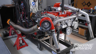
[Pat] Next on Engine Power our ultimate Ford 300 inline six project moves forward with the assembly of a long block, setting up a new valvetrain. [Frankie] And a whole lot of custom fabrication for our front accessory drive and the super trick sequential port e-f-i system.
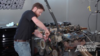
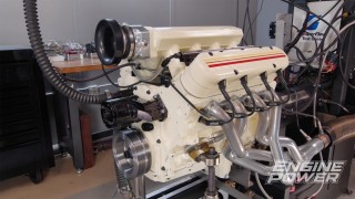
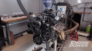
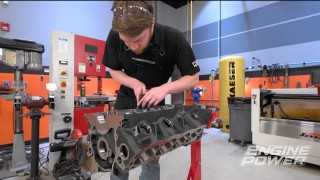
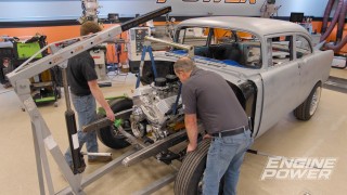
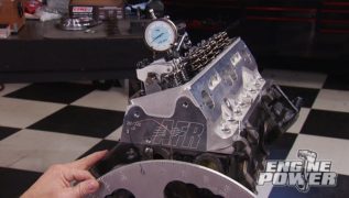
[Frankie] Hey everyone, welcome back to Engine Power. Today we are continuing on our ultimate turbocharged Ford 300 build. This is part two. In part one we got everything prepped, everything modified, and ready for assembly. In today's episode that's exactly what we're gonna do. We're gonna get this engine together and get it ready for a double dyno session where we're gonna run it both n/a and boosted. [Pat] Everything is looking really good and we're almost through but we're actually only halfway there. We still have to build an entire e-f-i wiring harness for our sequential e-f-i system and we have to build all new piping for our turbo system. But to show how we have arrived at this beautiful, white freshly painted, freshly machined engine check this out. We were very excited to do a forensic teardown on the first iteration of this build to see what condition the parts were in and how they held up to both a dyno thrashing and a chassis dyno session at the current power level. To our delight everything looked to be in great condition including the piston tops and skirts, the rod and main bearings, the cam and lifters, and the cylinder bores. [Frankie] After a quick wash we did a little reinforcing to the top of the cylinders by filling underneath the deck surface with some Moroso block filler. Then we torque plate honed the cylinders, modified and deburred the oil passageways, and final cleaned the block to prep it for a new super fresh white paint job. [Pat] Because our main bearing clearances are all set we can get right to assembly, and the first step is to slick up the bearings with a high quality assembly lube. We are using Hot Shot's Secret adrenaline assembly lubricant on all bearing surfaces. That paves the way for us to install our reground factory forged 3-980 stroked crankshaft. [Frankie] It gets lovingly and tenderly laid into place, making it ready for the main caps follow. After a dab of sealer at the parting line by the one piece rear main seal the number seven main cap gets lightly tapped into its register followed by the rest. And then the ARP main bolts get torqued in sequence to a final value of 80 pound feet. Next in the process is sliding in our fully custom billet hydraulic roller camshaft we had made by the valvetrain experts at Comp Cams. At this stage it is for mockup only but we will still use assembly lube on the entire surface. [Pat] Using a modern LS lobe design the duration at 50 thousandths lift is 221 degrees on the intake and 225 degrees on the exhaust with a 112 degree lobe separation angle. This cam has four degrees of advanced ground in and has lobe lifts of 358 thousandths on the intake and 360 thousandths on the exhaust respectfully, which puts our valve lift at 619 thousandths on the intake side and 623 thousandths on the exhaust. With a helical cut gear we carefully index both timing marks as it is installed. [Frankie] We will now install the number one piston and rod assembly in preparation for degreeing the cam. We degree every single cam we install whether you see us do it or not. Since there is no adjusting the intake center line with this setup that's why we have those four degrees ground in and it comes in at a 111.5 degree intake centerline thanks to the accuracy of Comp Cams and their strict quality control. [Pat] With that data acquired we pop in the remaining five assemblies and torque the ARP 2,000 rod bolts to 85 pound feet to achieve the proper bolts stretch between 60 and 64 ten thousandths. We check each bolt to ensure they are all within range. [Frankie] The next thing we're gonna do is determine where we need to place our cam sensor and the trigger for it. We're gonna do this very similar to our slant six. We're gonna put the sensor into the timing cover with a bung and we're gonna put a flying magnet target into the cam gear. That's way it's fixed, it can never move, and there's no chance of it getting messed up later. So Holley has very specific instructions on when this sensor needs to be triggered. In our case it's gonna be 240 degrees before top dead center on compression stroke. So we've got our degree wheel back on here. We're at top dead center on compression stroke. We're gonna roll it backwards to 240. The reason we need this is because this is gonna trigger to the e-c-u whether we are coming up on top dead center compression or on overlap. So we're at 240 degrees before top dead center compression and looking at our gear we're probably gonna put our trigger right in this webbing right here. That way it clears our front drive, timing pointer, and all that stuff. We're gonna go ahead and mark that one right there. Then what we're gonna do is pull the cam out. We'll find the center of that webbing. Drill it, tap it for a quarter-twenty, and install our magnet. We marked the exact spot for the magnet with a punch. Then carefully drill and tap the gear. Then the cam goes back in and is reindexed properly. This time the thrust plate bolts are torqued in place and the oil gallery plug installed. To find out exactly where to put the sensor bung we install this homemade quarter-twenty threaded transfer punch. Then take the stock aluminum timing cover, place it up there where it needs to go, and gently tap the cover to transfer a reference mark to the cover itself. From there we can now drill a pilot hole followed by a step drill the size of the hole for the weld in bung. With it precisely located we can weld it in place using our Forney tig welder. [ tig welder buzzing ] [Pat] Up next, we get our 300 prepped for big power with a c-n-c ported head and a solid valvetrain.
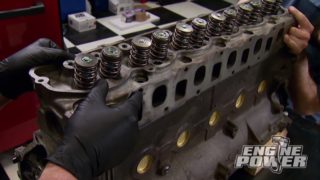
[Pat] With the short block pretty much buttoned up it's time to concentrate on the top end. The star of the show on this one is our cylinder. This is a fully c-n-c'ed new casting from Pro Max in Alabama. This features a late model casting heart shaped chamber bolt down rocker system. What's nice about this one it's fully c-n-c'ed in the chamber and ours comes out at 83.4cc. It is housed with some valves that are 1-940, 1-600. Swirl polished stainless valves are actually small block Chevy valves. This head flows 224 c-f-m at 700. Pretty spicy for a 300. Controlling those valves are some very high tech conical springs from Comp. They also have a tool steel retainer and a machined lock. These are 438 pounds per inch rate and we are setting them up at 1-825 installed height. That puts us right out 150 pounds of seat pressure and 415 pounds of open pressure at our lift. So what I'm gonna do is roll this over, put our other two springs on, and get this on the engine. A Fel Pro Severe Duty composite head gasket is laid down and a couple of studs installed for guiding the c-n-c ported Pro Max head onto our reinforced deck. The remainder of the ARP studs are twisted down and a coating of Ultra Torque Lube is applied to the threads and the top of the washer before the six point ARP 87-40 chromoly nuts are threaded down. The head is torqued in three steps ending in a final value of 80 pound feet. [Frankie] Now the cam sync magnet can go in for good, and with sealant and a gasket in place for the modified and freshly painted timing cover it can go on for real but stay slightly loose for now. We have our timing cover loosely set on there. The next thing we're gonna do is install our harmonic damper, and for this bigger, badder build we're gonna be stepping up to a viscous style Fluidampr. The reason we love using these is for one they are all s-f-i approved, which means they've been third party tested and if we decide to take this engine racing later on in the future we are good to go. Two, they cover a much wider range of damaging harmonic frequencies for the engine as opposed to an elastomer style. So they're gonna give us much better protection than the o-e damper would. And three, they don't require regular service or rebuilding like an elastomer style damper. If the viscous fluid is inside the damper and it's not leaking out then it's functioning just like it would on day one. Now this one is actually for a 302 internally balanced small block Ford. It has the four bolt hole aftermarket setup on the front. When we reached out to Fluidampr and told them we wanted to run a 302 damper they already knew we had to cut 250 thousandths off the back of it to have the right stand height and the right thread engagement for our crank bolt. To get this installed we already have lubrication on the seal, some anti-seize on the inside, and we're gonna press it on. With the damper on the cover bolts are tightened up, and then we'll rotate the engine until our flying magnet sensor is in line with the bung hole. Then we can thread the sensor in until it touches the flying magnet, back it off 60 thousandths, and lock it down. [Pat] We now have the green light to finish up the rest of the bottom of this bullet by bolting down our proven Melling high volume oil pump and the new pick up that matches our rear sump oil pan. The pan to pick up clearance checked out right at three-eighths of an inch. So a new one piece pan gasket is laid down and a new but modified for turbo drain and oil temp rear sump oil pan goes on with stainless ARP hardware. On to installing the Comp hydraulic roller lifters that slide in nicely thanks to Frankie's mods. That sets up for the three-eighths diameter 10-100 long 80 thousandths walled chromoly Comp push rods to get dropped into their cups. [Frankie] We are using a set of Scorpion 1.73 ratio bolt down aluminum roller rockers with 300 thousandths worth of shims and ARP bolts to secure them down. The shims are necessary to achieve the proper geometry and sweep on top of the valve. Plus because this is a non-adjustable setup the pushrod length and rocker shim setup are critical for the proper operation of the lifter. This keeps the valvetrain stable, accurate, and quiet. [Pat] We good! [Frankie] That looks nice. Coming up, we get our inline six customized and stylized.
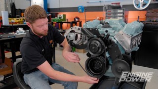
[Pat] It's time now to move to the outside of the engine. All of our internals are solid. Our valvetrain is all set up. So we are going to be starting off with the serpentine drive. This one in particular is from CVF Racing. This was specifically engineered for our 300, not only to look good but to be highly functional. We had to make a few modifications for our application but to tell you about that is. [Frankie] Me, that's right. Because we are using a unique setup we did have to change a few things. Mainly that's because we wanted to use a bunch of trick parts in this build. Like our Fluid Damper and this Holley 36 minus 1 crank trigger wheel. This is gonna give our e-c-u super accurate crank position data when the engine's running. This actually is centered on the hub of the Fluidampr but to get all of our pulley alignment correct and make sure we're not gonna have any belt walk or anything like that we had to actually machine the Fluidampr some more. So we had to take 905 thousandths off the back of the hub. The part that actually touches against the crank gear. And then we had to extend the seal surface forward and remove a little bit off the back face of the hub so it clears the timing cover. Then CVF sends a really nice hub adapter, which this basically does all the spacing for you if you're using an o-e damper, and we had to machine quite a bit off this one. It's usually almost three inches long and basically machined it down so that it goes inside the hub of the damper, and then our pulley clears not only our crank trigger but has the correct spacing for our alignment with the rest of the pulleys. So all this is super trick. It's very custom but it's gonna work perfectly once we get it on. With everything previously scienced out the entire assembly is easily bolted to the damper with the included allen head fasteners. [ Music ] Our crank trigger is gonna be actuating the sensor that came in the kit. This is Holley's 12 millimeter hall effect sensor. Now the brackets in the kit were designed for a small block Ford. So we just had to go ahead and build some. So we've got their sensor in their bracket tab here and then we built this quick piece of metal out of some three-sixteenths aluminum. This will rigidly mount the bracket. We've got the correct spacers to get it centered on the trigger wheel and this will mount the sensor on the leading edge of the seventh tooth after the missing one. That will tell the e-c-u exactly where t-d-c is. [ Music ] [Pat] What the f#$%^ are you doing?
[ Music ] [ cheering ] [Frankie] It bolts down to the timing cover using two existing holes. Next the gap on the sensor is set precisely to 50 thousandths of an inch for accurate reading. [Pat] Before the drive assembly goes on we'll install the water neck because at this point it's easier to get at. A new gasket goes on the freshly painted water pump. Then the entire bracket assembly gets installed for good and cinched down. The first pulley to go on is the one for the water pump, which is ribbed because it is still standard rotation. That is followed by the new power steering pump with an integrated reservoir and this very trick bolt on pulley. After that the one wire 140 amp alternator and the sanden style a/c compressor are put in place. Last to go on is a new belt tensioner and belt. Plus all the included billet covers that really sets this assembly off. The freshened up lifter side cover is next on the agenda to get installed. We added some stainless ARP studs to the block for ease of installation and to help facilitate what comes next, our custom aluminum coil mount plate. We cut up some Holley coil mount brackets for an LS and welded them to a shaped sheet of three-sixteenths aluminum plate. Stainless nuts are snugged up and that lets us put our Holley Smart Coils right where we want them. [Pat] Since we are coil near plug ignition we have no use for a distributor any more but we need a way to drive the oil pump. So we took a stock distributor, sawed it off, made a cover for it, and then put a bronze gear on it for our billet steel cam. This will go in. It doesn't need to be timed. All it needs to do is index with the cam, run through the driveshaft, do the oil pump, and get it to run. With Hot Shot's secret assembly lube on the gear and the ends of the hex shaft the new setup goes in just like the distributor would and gets secured with a stock hold down. A billet 90 degree Summit oil filter adapter housing will make future oil changes a lot less messy. [Frankie] A one piece valve cover gasket with compression stops gets laid on the head in preparation for this super cool finned cast aluminum valve cover courtesy of Offenhauser. More stainless ARP fasteners keep it in place. We did weld on a couple of dash-12 a-n fittings so we can run lines to the headers for active crankcase ventilation. That's nice! [Pat] Next up, we're not gonna lie. [Frankie] It's all e-f-i.
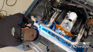
[Frankie] Our 300 is coming along very nicely and the next thing we're gonna do is put our intake and header. If you'll remember this was an Offenhauser C-series HD manifold that was converted to port e-f-i by Wilson Manifolds. We have really good fuel control now. They did a little bit of work inside the plenum as well, and with this HD manifold we don't have any heat risers. So it's a nice slim, sleek design. This'll go right on and then our header will follow. [Pat] We are making this a two person job because getting everything aligned before the fasteners go in can be a challenge. This header has previously been clearance for the former build. So a bit of persuasion gets it bolted in place with little effort. [Frankie] The next thing we're gonna do is a big one and that is building the e-f-i system for our Ford 300, and to do that we are gonna be using all Holley components because Holley has been one of the leaders in e-f-i for switching engines over to either throttle body or multi-port fuel injection. So starting out it's all gonna be controlled by their Holley HP ECU. This is a really compact and robust e-c-u. It has self-learning fuel control. It has boost control, nitrous control, two steps, launch control, all of that built in. For the harness we're gonna be using one of their flying lead harnesses. It basically has the two connectors that go into the e-c-u, a fuse, and a relay, and the can connection. Then everything else is just unterminated wires. So we can lay it out. Figure where we need everything to go and then terminate it from there. We also have the main power harness. We have an MSD four channel solid state relay for any power distribution needs that we have. We have all the connectors that we need for every sensor that the e-c-u needs to see. For boost control we are gonna be using one of their single three port mack valves. We have the correct oxygen sensor for our harness and our e-c-u. Then the big thing here is a set of eight flow matched Holley injectors. These are 100 pound per hour injectors that are dynamically flow matched within one percent of each other. We will also be building an injector harness for those and we'll tie that into their main harness later. It sounds like a lot and it is but if you have a good wiring diagram, follow their instructions closely, it's really not that complicated. We'll get started, get our sensors installed, and then start laying out some harness. First to go in are the three and a half bar crankcase pressure sensor and the zero to 100 p-s-i oil pressure sensor. We modified a fuel pump block off plate to monitor the crank case pressure. Next a two inch Wilson open spacer goes on to allow our Holley LS to 41-50 adapter elbow to clear the injector rail. The elbow is cinched down with ARP studs and nuts. That is followed by installing the inlet air temp sensor and the three and a half bar map sensor in the pre-tapped holes in its base. [Pat] Man things are coming together great and it's time to stick some injectors in that rail but that gives us an opportunity to tell you some injector tech and that is gonna be the subject of today's Summit Tech Tip. What we're gonna talk about is the difference between high and low impedance injectors. You've probably heard that term before. That is the amount of resistance across the two contacts in the injector in ohms. High impedance injectors, we'll start with that. They run between 10 and 16 ohms if you measure it. The reason a high impedance injector is used usually by the o-e-m is because one, it is cheaper to manufacture. The drive that is required for the e-c-u doesn't get as expensive to make when it is a high impedance injector. Also they run very cool because they run at a lower current. That is better for durability and longevity. They still flow good and you can still get a high performance high impedance injector. For instance these new injectors from Trick Flow are a high impedance injector. They flow 110 pounds per hour. Now we're gonna talk about a low impedance injector. That operates at a lower amount of ohms, between two and eight ohms. What that does is a few things. One, they take a little more current to activate but if you've heard the term peak and hold that's another term for a low impedance injector. They are made to flow more. They're a little bit more expensive because the driver is a little bit more expensive to manufacture for the e-c-u. These are typically used in pretty much all high performance applications. If you have any questions about what injector you should run in your particular application you can contact the experts at Summit Racing Equipment. With the fuel rail loaded up with Holley Terminator flow matched 100 pound per hour injectors it is carefully pushed into the intake making sure all of the injectors are fully seated. Two ARP stainless fasteners secure it in place. [Frankie] Then it is time for the real fun to begin. Laying out the unterminated harness to start the pain staking task of connecting everything. The Holley HP ECU is plugged in and the first order of business is building the injector harness. For this job having the right connectors and a proper crimping tool makes the work go way easier. This process usually takes a few days but if you take your time, label everything properly, and follow a wiring diagram you can get through it just fine. [Pat] Cannot see any of this. [Frankie] Probably because you don't have your glasses on. [Pat] You're probably right. [Frankie] It may not look like we have made huge progress on our harness but we actually have. We have all of our wires labeled for where they need to go. We've gone ahead and made an injector harness. We've made a coil harness. Basically all that's left is to terminate all the sensor connections and loom it. But for today we are out of time. So I'm gonna go ahead and get this finished and next time. [Pat] It is dyno time. Remember we're gonna run this in both configurations. Both naturally aspirated like it is to get a good number and then put it on the artificial atmosphere to get that big boosted number. To check something out like this or anything else we've done just go to Powernation.
Show Full Transcript
[Pat] Next on Engine Power our ultimate Ford 300 inline six project moves forward with the assembly of a long block, setting up a new valvetrain. [Frankie] And a whole lot of custom fabrication for our front accessory drive and the super trick sequential port e-f-i system.
[Frankie] Hey everyone, welcome back to Engine Power. Today we are continuing on our ultimate turbocharged Ford 300 build. This is part two. In part one we got everything prepped, everything modified, and ready for assembly. In today's episode that's exactly what we're gonna do. We're gonna get this engine together and get it ready for a double dyno session where we're gonna run it both n/a and boosted. [Pat] Everything is looking really good and we're almost through but we're actually only halfway there. We still have to build an entire e-f-i wiring harness for our sequential e-f-i system and we have to build all new piping for our turbo system. But to show how we have arrived at this beautiful, white freshly painted, freshly machined engine check this out. We were very excited to do a forensic teardown on the first iteration of this build to see what condition the parts were in and how they held up to both a dyno thrashing and a chassis dyno session at the current power level. To our delight everything looked to be in great condition including the piston tops and skirts, the rod and main bearings, the cam and lifters, and the cylinder bores. [Frankie] After a quick wash we did a little reinforcing to the top of the cylinders by filling underneath the deck surface with some Moroso block filler. Then we torque plate honed the cylinders, modified and deburred the oil passageways, and final cleaned the block to prep it for a new super fresh white paint job. [Pat] Because our main bearing clearances are all set we can get right to assembly, and the first step is to slick up the bearings with a high quality assembly lube. We are using Hot Shot's Secret adrenaline assembly lubricant on all bearing surfaces. That paves the way for us to install our reground factory forged 3-980 stroked crankshaft. [Frankie] It gets lovingly and tenderly laid into place, making it ready for the main caps follow. After a dab of sealer at the parting line by the one piece rear main seal the number seven main cap gets lightly tapped into its register followed by the rest. And then the ARP main bolts get torqued in sequence to a final value of 80 pound feet. Next in the process is sliding in our fully custom billet hydraulic roller camshaft we had made by the valvetrain experts at Comp Cams. At this stage it is for mockup only but we will still use assembly lube on the entire surface. [Pat] Using a modern LS lobe design the duration at 50 thousandths lift is 221 degrees on the intake and 225 degrees on the exhaust with a 112 degree lobe separation angle. This cam has four degrees of advanced ground in and has lobe lifts of 358 thousandths on the intake and 360 thousandths on the exhaust respectfully, which puts our valve lift at 619 thousandths on the intake side and 623 thousandths on the exhaust. With a helical cut gear we carefully index both timing marks as it is installed. [Frankie] We will now install the number one piston and rod assembly in preparation for degreeing the cam. We degree every single cam we install whether you see us do it or not. Since there is no adjusting the intake center line with this setup that's why we have those four degrees ground in and it comes in at a 111.5 degree intake centerline thanks to the accuracy of Comp Cams and their strict quality control. [Pat] With that data acquired we pop in the remaining five assemblies and torque the ARP 2,000 rod bolts to 85 pound feet to achieve the proper bolts stretch between 60 and 64 ten thousandths. We check each bolt to ensure they are all within range. [Frankie] The next thing we're gonna do is determine where we need to place our cam sensor and the trigger for it. We're gonna do this very similar to our slant six. We're gonna put the sensor into the timing cover with a bung and we're gonna put a flying magnet target into the cam gear. That's way it's fixed, it can never move, and there's no chance of it getting messed up later. So Holley has very specific instructions on when this sensor needs to be triggered. In our case it's gonna be 240 degrees before top dead center on compression stroke. So we've got our degree wheel back on here. We're at top dead center on compression stroke. We're gonna roll it backwards to 240. The reason we need this is because this is gonna trigger to the e-c-u whether we are coming up on top dead center compression or on overlap. So we're at 240 degrees before top dead center compression and looking at our gear we're probably gonna put our trigger right in this webbing right here. That way it clears our front drive, timing pointer, and all that stuff. We're gonna go ahead and mark that one right there. Then what we're gonna do is pull the cam out. We'll find the center of that webbing. Drill it, tap it for a quarter-twenty, and install our magnet. We marked the exact spot for the magnet with a punch. Then carefully drill and tap the gear. Then the cam goes back in and is reindexed properly. This time the thrust plate bolts are torqued in place and the oil gallery plug installed. To find out exactly where to put the sensor bung we install this homemade quarter-twenty threaded transfer punch. Then take the stock aluminum timing cover, place it up there where it needs to go, and gently tap the cover to transfer a reference mark to the cover itself. From there we can now drill a pilot hole followed by a step drill the size of the hole for the weld in bung. With it precisely located we can weld it in place using our Forney tig welder. [ tig welder buzzing ] [Pat] Up next, we get our 300 prepped for big power with a c-n-c ported head and a solid valvetrain.
[Pat] With the short block pretty much buttoned up it's time to concentrate on the top end. The star of the show on this one is our cylinder. This is a fully c-n-c'ed new casting from Pro Max in Alabama. This features a late model casting heart shaped chamber bolt down rocker system. What's nice about this one it's fully c-n-c'ed in the chamber and ours comes out at 83.4cc. It is housed with some valves that are 1-940, 1-600. Swirl polished stainless valves are actually small block Chevy valves. This head flows 224 c-f-m at 700. Pretty spicy for a 300. Controlling those valves are some very high tech conical springs from Comp. They also have a tool steel retainer and a machined lock. These are 438 pounds per inch rate and we are setting them up at 1-825 installed height. That puts us right out 150 pounds of seat pressure and 415 pounds of open pressure at our lift. So what I'm gonna do is roll this over, put our other two springs on, and get this on the engine. A Fel Pro Severe Duty composite head gasket is laid down and a couple of studs installed for guiding the c-n-c ported Pro Max head onto our reinforced deck. The remainder of the ARP studs are twisted down and a coating of Ultra Torque Lube is applied to the threads and the top of the washer before the six point ARP 87-40 chromoly nuts are threaded down. The head is torqued in three steps ending in a final value of 80 pound feet. [Frankie] Now the cam sync magnet can go in for good, and with sealant and a gasket in place for the modified and freshly painted timing cover it can go on for real but stay slightly loose for now. We have our timing cover loosely set on there. The next thing we're gonna do is install our harmonic damper, and for this bigger, badder build we're gonna be stepping up to a viscous style Fluidampr. The reason we love using these is for one they are all s-f-i approved, which means they've been third party tested and if we decide to take this engine racing later on in the future we are good to go. Two, they cover a much wider range of damaging harmonic frequencies for the engine as opposed to an elastomer style. So they're gonna give us much better protection than the o-e damper would. And three, they don't require regular service or rebuilding like an elastomer style damper. If the viscous fluid is inside the damper and it's not leaking out then it's functioning just like it would on day one. Now this one is actually for a 302 internally balanced small block Ford. It has the four bolt hole aftermarket setup on the front. When we reached out to Fluidampr and told them we wanted to run a 302 damper they already knew we had to cut 250 thousandths off the back of it to have the right stand height and the right thread engagement for our crank bolt. To get this installed we already have lubrication on the seal, some anti-seize on the inside, and we're gonna press it on. With the damper on the cover bolts are tightened up, and then we'll rotate the engine until our flying magnet sensor is in line with the bung hole. Then we can thread the sensor in until it touches the flying magnet, back it off 60 thousandths, and lock it down. [Pat] We now have the green light to finish up the rest of the bottom of this bullet by bolting down our proven Melling high volume oil pump and the new pick up that matches our rear sump oil pan. The pan to pick up clearance checked out right at three-eighths of an inch. So a new one piece pan gasket is laid down and a new but modified for turbo drain and oil temp rear sump oil pan goes on with stainless ARP hardware. On to installing the Comp hydraulic roller lifters that slide in nicely thanks to Frankie's mods. That sets up for the three-eighths diameter 10-100 long 80 thousandths walled chromoly Comp push rods to get dropped into their cups. [Frankie] We are using a set of Scorpion 1.73 ratio bolt down aluminum roller rockers with 300 thousandths worth of shims and ARP bolts to secure them down. The shims are necessary to achieve the proper geometry and sweep on top of the valve. Plus because this is a non-adjustable setup the pushrod length and rocker shim setup are critical for the proper operation of the lifter. This keeps the valvetrain stable, accurate, and quiet. [Pat] We good! [Frankie] That looks nice. Coming up, we get our inline six customized and stylized.
[Pat] It's time now to move to the outside of the engine. All of our internals are solid. Our valvetrain is all set up. So we are going to be starting off with the serpentine drive. This one in particular is from CVF Racing. This was specifically engineered for our 300, not only to look good but to be highly functional. We had to make a few modifications for our application but to tell you about that is. [Frankie] Me, that's right. Because we are using a unique setup we did have to change a few things. Mainly that's because we wanted to use a bunch of trick parts in this build. Like our Fluid Damper and this Holley 36 minus 1 crank trigger wheel. This is gonna give our e-c-u super accurate crank position data when the engine's running. This actually is centered on the hub of the Fluidampr but to get all of our pulley alignment correct and make sure we're not gonna have any belt walk or anything like that we had to actually machine the Fluidampr some more. So we had to take 905 thousandths off the back of the hub. The part that actually touches against the crank gear. And then we had to extend the seal surface forward and remove a little bit off the back face of the hub so it clears the timing cover. Then CVF sends a really nice hub adapter, which this basically does all the spacing for you if you're using an o-e damper, and we had to machine quite a bit off this one. It's usually almost three inches long and basically machined it down so that it goes inside the hub of the damper, and then our pulley clears not only our crank trigger but has the correct spacing for our alignment with the rest of the pulleys. So all this is super trick. It's very custom but it's gonna work perfectly once we get it on. With everything previously scienced out the entire assembly is easily bolted to the damper with the included allen head fasteners. [ Music ] Our crank trigger is gonna be actuating the sensor that came in the kit. This is Holley's 12 millimeter hall effect sensor. Now the brackets in the kit were designed for a small block Ford. So we just had to go ahead and build some. So we've got their sensor in their bracket tab here and then we built this quick piece of metal out of some three-sixteenths aluminum. This will rigidly mount the bracket. We've got the correct spacers to get it centered on the trigger wheel and this will mount the sensor on the leading edge of the seventh tooth after the missing one. That will tell the e-c-u exactly where t-d-c is. [ Music ] [Pat] What the f#$%^ are you doing?
[ Music ] [ cheering ] [Frankie] It bolts down to the timing cover using two existing holes. Next the gap on the sensor is set precisely to 50 thousandths of an inch for accurate reading. [Pat] Before the drive assembly goes on we'll install the water neck because at this point it's easier to get at. A new gasket goes on the freshly painted water pump. Then the entire bracket assembly gets installed for good and cinched down. The first pulley to go on is the one for the water pump, which is ribbed because it is still standard rotation. That is followed by the new power steering pump with an integrated reservoir and this very trick bolt on pulley. After that the one wire 140 amp alternator and the sanden style a/c compressor are put in place. Last to go on is a new belt tensioner and belt. Plus all the included billet covers that really sets this assembly off. The freshened up lifter side cover is next on the agenda to get installed. We added some stainless ARP studs to the block for ease of installation and to help facilitate what comes next, our custom aluminum coil mount plate. We cut up some Holley coil mount brackets for an LS and welded them to a shaped sheet of three-sixteenths aluminum plate. Stainless nuts are snugged up and that lets us put our Holley Smart Coils right where we want them. [Pat] Since we are coil near plug ignition we have no use for a distributor any more but we need a way to drive the oil pump. So we took a stock distributor, sawed it off, made a cover for it, and then put a bronze gear on it for our billet steel cam. This will go in. It doesn't need to be timed. All it needs to do is index with the cam, run through the driveshaft, do the oil pump, and get it to run. With Hot Shot's secret assembly lube on the gear and the ends of the hex shaft the new setup goes in just like the distributor would and gets secured with a stock hold down. A billet 90 degree Summit oil filter adapter housing will make future oil changes a lot less messy. [Frankie] A one piece valve cover gasket with compression stops gets laid on the head in preparation for this super cool finned cast aluminum valve cover courtesy of Offenhauser. More stainless ARP fasteners keep it in place. We did weld on a couple of dash-12 a-n fittings so we can run lines to the headers for active crankcase ventilation. That's nice! [Pat] Next up, we're not gonna lie. [Frankie] It's all e-f-i.
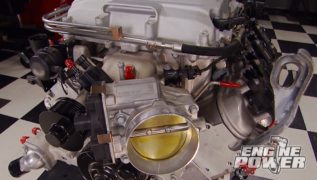
[Frankie] Our 300 is coming along very nicely and the next thing we're gonna do is put our intake and header. If you'll remember this was an Offenhauser C-series HD manifold that was converted to port e-f-i by Wilson Manifolds. We have really good fuel control now. They did a little bit of work inside the plenum as well, and with this HD manifold we don't have any heat risers. So it's a nice slim, sleek design. This'll go right on and then our header will follow. [Pat] We are making this a two person job because getting everything aligned before the fasteners go in can be a challenge. This header has previously been clearance for the former build. So a bit of persuasion gets it bolted in place with little effort. [Frankie] The next thing we're gonna do is a big one and that is building the e-f-i system for our Ford 300, and to do that we are gonna be using all Holley components because Holley has been one of the leaders in e-f-i for switching engines over to either throttle body or multi-port fuel injection. So starting out it's all gonna be controlled by their Holley HP ECU. This is a really compact and robust e-c-u. It has self-learning fuel control. It has boost control, nitrous control, two steps, launch control, all of that built in. For the harness we're gonna be using one of their flying lead harnesses. It basically has the two connectors that go into the e-c-u, a fuse, and a relay, and the can connection. Then everything else is just unterminated wires. So we can lay it out. Figure where we need everything to go and then terminate it from there. We also have the main power harness. We have an MSD four channel solid state relay for any power distribution needs that we have. We have all the connectors that we need for every sensor that the e-c-u needs to see. For boost control we are gonna be using one of their single three port mack valves. We have the correct oxygen sensor for our harness and our e-c-u. Then the big thing here is a set of eight flow matched Holley injectors. These are 100 pound per hour injectors that are dynamically flow matched within one percent of each other. We will also be building an injector harness for those and we'll tie that into their main harness later. It sounds like a lot and it is but if you have a good wiring diagram, follow their instructions closely, it's really not that complicated. We'll get started, get our sensors installed, and then start laying out some harness. First to go in are the three and a half bar crankcase pressure sensor and the zero to 100 p-s-i oil pressure sensor. We modified a fuel pump block off plate to monitor the crank case pressure. Next a two inch Wilson open spacer goes on to allow our Holley LS to 41-50 adapter elbow to clear the injector rail. The elbow is cinched down with ARP studs and nuts. That is followed by installing the inlet air temp sensor and the three and a half bar map sensor in the pre-tapped holes in its base. [Pat] Man things are coming together great and it's time to stick some injectors in that rail but that gives us an opportunity to tell you some injector tech and that is gonna be the subject of today's Summit Tech Tip. What we're gonna talk about is the difference between high and low impedance injectors. You've probably heard that term before. That is the amount of resistance across the two contacts in the injector in ohms. High impedance injectors, we'll start with that. They run between 10 and 16 ohms if you measure it. The reason a high impedance injector is used usually by the o-e-m is because one, it is cheaper to manufacture. The drive that is required for the e-c-u doesn't get as expensive to make when it is a high impedance injector. Also they run very cool because they run at a lower current. That is better for durability and longevity. They still flow good and you can still get a high performance high impedance injector. For instance these new injectors from Trick Flow are a high impedance injector. They flow 110 pounds per hour. Now we're gonna talk about a low impedance injector. That operates at a lower amount of ohms, between two and eight ohms. What that does is a few things. One, they take a little more current to activate but if you've heard the term peak and hold that's another term for a low impedance injector. They are made to flow more. They're a little bit more expensive because the driver is a little bit more expensive to manufacture for the e-c-u. These are typically used in pretty much all high performance applications. If you have any questions about what injector you should run in your particular application you can contact the experts at Summit Racing Equipment. With the fuel rail loaded up with Holley Terminator flow matched 100 pound per hour injectors it is carefully pushed into the intake making sure all of the injectors are fully seated. Two ARP stainless fasteners secure it in place. [Frankie] Then it is time for the real fun to begin. Laying out the unterminated harness to start the pain staking task of connecting everything. The Holley HP ECU is plugged in and the first order of business is building the injector harness. For this job having the right connectors and a proper crimping tool makes the work go way easier. This process usually takes a few days but if you take your time, label everything properly, and follow a wiring diagram you can get through it just fine. [Pat] Cannot see any of this. [Frankie] Probably because you don't have your glasses on. [Pat] You're probably right. [Frankie] It may not look like we have made huge progress on our harness but we actually have. We have all of our wires labeled for where they need to go. We've gone ahead and made an injector harness. We've made a coil harness. Basically all that's left is to terminate all the sensor connections and loom it. But for today we are out of time. So I'm gonna go ahead and get this finished and next time. [Pat] It is dyno time. Remember we're gonna run this in both configurations. Both naturally aspirated like it is to get a good number and then put it on the artificial atmosphere to get that big boosted number. To check something out like this or anything else we've done just go to Powernation.
Engine Power Featured Projects
Engine Power Builds




Want more content like this?
Join the PowerNation Email NewsletterParts Used In This Episode


Comp Cams
COMP Cams Custom Grind Camshaft
Comp Cams
COMP Cams OD Conical Springs
Comp Cams
COMP Cams Pushrods
Comp Cams
COMP Cams Retro-Fit Hydraulic Roller Lifter Pair for Ford FE
CVF Racing
Crank Pulley
CVF Racing
Crank Pulley Adapter
CVF Racing
Ford Straight Six All Inclusive Serpentine System
Holley
LS 24150 Adapter Elbow
Melling
High-Volume Oil Pump
Melling
Oil Pump Screen Assembly
Offenhauser
Offenhauser For 300 High Rise Valve Cover
Offenhauser
Offenhauser Ford L6 Intake Manifold
ProMaxx Performance
Promaxx CNC Ported Cylinder Heads
WILSON MANIFOLDS
2-IN Open Spacer