In This Episode
- 0:01 Introduction and Overview of the Engine Build
- 2:03 Engine History and Previous Configurations
- 4:10 Preparing the Engine for Rebuilding
- 6:01 Disassembling the Engine
- 9:01 Inspecting Engine Components
- 11:01 Rebuilding the Engine: New Parts and Modifications
- 14:00 Preparing the Block for Painting
- 15:01 Painting the Engine
- 17:09 Assembling the Engine
- 20:21 Finalizing the Engine Build and Future Plans
Video Transcript
[Frankie] You're watching Powernation!
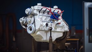
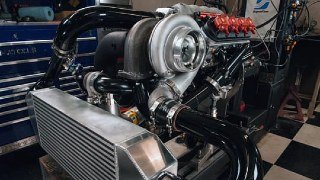
[Pat] Today on Engine Power we are on the special projects unit where we cook up a 632 cubic inch big block Chevy to be big torque high tech pump gas tire killer. [Frankie] In today's show we're gonna start the transformation getting this engine prepped and into short block form with some high tech parts and a little bit of bling to get it ready for its new modern muscle truck home. ♪ ♪
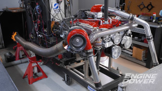
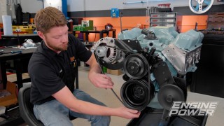
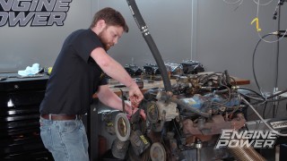
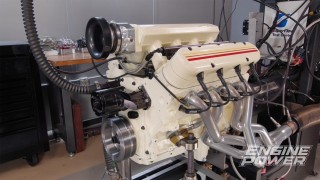
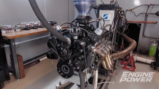
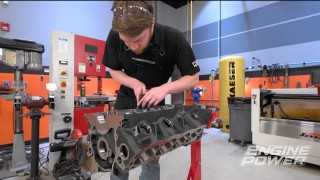
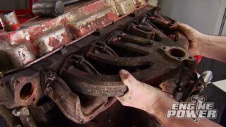
♪ ♪ [ drill humming ] [Pat] Hey everyone, welcome to Engine Power. This is a brand new season, brand new episode, and a brand new engine build but the engine itself not so new. This engine has been kicking around our shop for a long time and has been in a couple of different configurations. From a race burning engine that makes well over 1,000 horsepower to a rot gut pump gas burning engine that is a good street bullet, but today it has finally found its final purpose. [Frankie] Today we are gonna take this big block Chevy, which is 632 cubic inches, and we're gonna put it in its final form. So this engine is 4.600 bore, 4.750 inch stroke. It's based on a Gen-6 big block Chevy block. But like Pat said, it has had several different parts run through it throughout the years and today we're gonna put even more parts in it and get it ready for its final life as a sweet street engine. So before we get started we're gonna show you how this engine started out, how many parts we've run through it, and then we'll get into what we're gonna do today. [ engine revving ] [Frankie] The first time you saw this engine it was being set up as a high horsepower mud truck bullet with over 15-to-1 static compression ratio and produced 1,022 horsepower and 821 pound feet with an r-p-m ceiling of 7,500. A BluePrint tall deck 4.600 bore big block Chevy engine block set the foundation and was filled with a 4,750 stroke forged crank. A set of H-beam 6.700 long rods and 42cc domed pistons rounded out the short block along with an aggressive solid roller bump stick driven by a Jesel timing belt drive. AFR 385cc aluminum heads topped it off and Jesel Sportsman 1.8-ratio rockers actuated the valves. An Edelbrock Super Victor-2 finished the induction with a Holley 4500 Sniper throttle body to make those big numbers on the dyno. [Pat] In the second version the engine was tamed down into a high torque street monster that could eat pump gas and blow the tires off of anything. The domed pistons were swapped out for a much lower compression 14cc dish for a 9.57-to-1 measured static compression ratio that would allow it to run on 93 octane. The cam shaft was also swapped for a smaller solid roller to lower the r-p-m range and put the red line at 6,500 r-p-m. All the other parts were refreshed and reused, and on the dyno it churned out 850 horsepower and 746 pound feet of torque. [Frankie] To make the changes we want for the final iteration of this power plant we're gonna be tearing it completely apart. Along the way we will be inspecting everything for an abnormal wear or potential failure points that need to be resolved. [Pat] Clean, one owner. [Frankie] After prying off the intake the valve train can be removed cylinder by cylinder with each one set at t-d-c compression stroke to remove any spring pressure before the rockers come off. All the valve train including the lifters is kept organized and in order for diagnosis and reassembly later on. The Jesel rocker stands do have to be removed to get access to the head stud nuts taking to care to keep the shims underneath orderly. [Pat] All of the head studs can be loosened from the outside in and removed from the block before pulling the cylinder heads to get the first look at the condition of the cylinders. Considering the abuse this thing has taken on the dyno they look excellent with minimal wear and a considerable amount of cross hatch still in the bore. Making our way to the bottom of the engine we can remove the electric water pump, crank trigger setup, and pull the harmonic damper off the crank snout. All of the ARP oil pan bolts can be removed and the oil pan gently tapped to break the seal and lower it down. [Frankie] After flipping the engine over we can remove the oil pump and then start removing the rod and piston assembly. We'll loosen the rod bolts on that crank throw, tap them with a rubber mallet to separate the rod and cap, and then we can remove the cap completely and gently push the rod down and out of the bores. With all eight assemblies removed we can loosen the left hand thread cam gear bolt, remove the timing set, and pull the crank gear off the snout with a steering wheel puller. After gently prying the timing cover off the cam shaft can be slid out. This one has specs of 274/284 at 50 and is set on a 114 degree lobe separation angle. It has a four-seven firing order swap and lift at the valve is 772 thousandths of an inch. It looks excellent and will be put on the shelf for a later build. Finally the half inch main bolts can be broke loose, zipped out, and the main caps carefully pried out of their registers so we can lift out the hefty 4.750 inch stroke crank. [Pat] Once again, things you look for. Underneath the cap make sure there's no fretting. When it's fretted like that that means it has gone into detonation, the caps are moving around probably because it was mis-tuned. Everything is nice on these, bearings look great. [Frankie] I would say for the health it's in it's really good. Probably gonna reuse a decent number of these, and then we'll just add all our new stuff. Up next, we get this engine refreshed and rebalanced to get this rebuild kicked off.
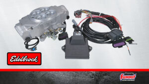
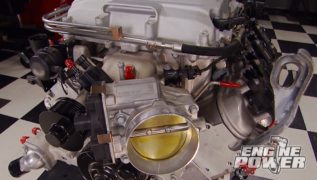
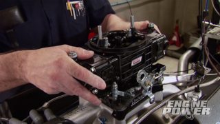
[Pat] The first thing we're gonna do is tell you about all the new parts we're using to reconfigure our 632 to its new duty as a street pump gas engine. First thing we're gonna do is actually gonna up the compression ratio. That sounds a little counterintuitive but let me explain. We had a 14cc effective dish on the piston. So we're gonna be raising it to a 10cc effective dome with this new Mahle PowerPak piston kit. Also we are going to go from a solid roller cam shaft to a hydraulic roller valve train. We had a new cam ground up by Comp with hydraulic roller lobes for our application and also we're putting a set of their Comp hydraulic roller lifters in. Plus we have to change the spring pressure in the heads. They're set up for a solid roller. So they have too much seat and open pressure. So we have a new set of springs from AFR to fit the bill but that is just half of it. [Frankie] The big upgrade on this engine is gonna be switching it to multi-port fuel injection and coil near plug ignition because that's what the guys want for the application that it's going in. To do that it's actually pretty easy because parts are readily available. It's all gonna be based around Holley's Terminator-X e-c-u. To get the manifold switched over we actually can get one right off the shelf. This is an Edelbrock Super Victor e-f-i manifold for a tall deck big block Chevy. We got the matching fuel rails and it has a 4500 flange on the top. So we have a Wilson Manifolds two inch bore 4500 flange throttle body with their IAC and TPS already on there. We have a set of 120 pound injectors so we can run any fuel we want. We have a set of Holley e-f-i Smart Coils for our coil near plug ignition, and to give the e-c-u everything it needs as far as timing for sequential fuel and ignition we have a 36 minus 1 big block Chevy crank trigger kit and an MSD billet cam sync because we don't need a distributor. So we just want to show you guys all the cool parts we're actually gonna be installing on this. Now we actually have to get back to work. ♪ ♪ [ drill humming ] [Pat] To prep the block itself we are going to quickly freshen up the bores with a 320 grit four and five-eighths inch flex hone making sure to use a sufficient amount of lubricant during the process. This will give us a fresh surface finish for our new rings to seal against and clean up any minor imperfections in the cylinder. Then we can remove all of the threaded oil gallery plugs and put the block in our JRI jet washer for a thorough cleaning. [Frankie] Now that we have our block prepped the next thing we're gonna do is balance the rotating assembly. Because we are changing the piston it's not too much different. It's about 16 grams difference between the old one and the new one, but we do want to rebalance the assembly to make sure that it is correct. I've gone ahead and got a bunch of the weights already and wrapping up now. We'll get some bob weights made, get them on our crank, and then do our first spin and see where we're at. The CWT software will automatically calculate the bob weight for you. So all we have to do is enter in the weight of each individual component. Then we can assemble and install a bob weight on each crank pin and get our first spin going. ♪ ♪ Not that bad. That's about what we thought it would be being such a slight difference between the two pistons. So we are 22 grams on the rear, 12 on the front, but as far as location the front is not bad. It's right on the edge of the counterweight but the back is gonna be a minor issue because for a moving weight you can't actually remove it from the counterweight side. It actually wants you to remove it from the rod journal side. So we're gonna have to figure out a way to add weight to the counterweight. Maybe fill in a few holes that are there and see how close that gets us. It probably will do it for us but we'll probably start there that way we can add material all at once and then remove material all at once. In order to add the small amount of weight needed for this job we will use the existing holes in the counterweights and fill them by welding them up. Using eighth inch ER-70-S filler material and even heat we can build up a few of the holes above the surface. [ grinder buzzing ] [Frankie] And then grind them down flush for a nice, smooth finish. This puts the heavy side of the imbalance back on the counterweight. So with a few smaller and well placed drill holes we can quickly bring the imbalance down within our target. Alright, we'll take that. That is .107 ounce inch on the front, .147 ounce inch on the rear. They are 184 degrees apart from each other. So they cancel out to .041 ounce inch on the center of the crank. We'll save that as our last spin and that's gonna work really good for this application. We didn't make a huge change because the pistons are very similar in size but it's still really important to have this done because if we look at the forces on the crank from before and after even just before if we had left it alone it would have been 178 pounds of force at 6,000 r-p-m. Now by actually balancing the crank we've minimized that down to nine and a half pounds of force. Huge, huge difference even though the pistons are very similar. So definitely something that needed to be done. Now it's finished up and we can move on. Coming up, our engine gets well read, well "red".
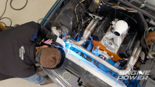
[Frankie] The next thing we want to do on our 632 big block Chevy is paint it but we can't do that yet because we need to modify our valve covers to mount our Holley EFI Smart Coils. Now the easiest way we found to do this is use Holley's coil relocation brackets. These are made so you can mount your coils anywhere inside the engine bay, but we can actually take them and weld them directly to our valve covers because they're made of aluminum. So what we're gonna do is get these prepped, get them centered where we like, and then we'll just weld them directly to them. [Pat] We don't need the mounting tabs on the coil brackets. So to get a cleaner look we can cut off the additional material using the band saw. With a flap disc we can nicely smooth out our cuts and remove the paint from the sections we will be welding on. After cleaning the bare aluminum with lacquer thinner to remove any contaminants we can locate the brackets where we want on the valve cover, clamp them down, and evenly tack them into place. After that it's just a matter of fully welding the bracket in several spots to provide support and now we have a clean and simple mounting solution for our 632's coil near plug ignition. The last thing we're gonna do before we assemble our engine is get it painted. We're gonna put some POR engine enamel on it and make it look great, but before we do that we have to get it cleaned up so we get good adhesion. So the first thing we are gonna do is clean all the parts we're painting with POR's Cleaner/Degreaser. What that's gonna do is make sure the surface is prepped properly and everything will stick to it. Gets all that grease and oil out, gives us a good surface. Then before we paint it we're gonna hit it with POR's Metal Prep. That promotes the adhesion of the paint. So all we've gotta do is get to cleaning. [Frankie] First we will spray down all the parts to remove any debris, and then we can start applying the cleaner/degreaser. [ water sloshing ] [Frankie] This is mixed with warm water in a four to one ratio, and we can use a stiff bristle brush to give the pieces a thorough scrubbing. We don't want any oils or grease that could ruin our paint job to be left on the surfaces. So we'll go over everything twice before giving it another rinse with the water hose. [Pat] The Metal Prep is used straight from the bottle and can be liberally applied with a brush to all the surfaces that will receive paint. To help protect the cylinder bores and bearing surfaces we heavily wiped them down with lubricant before we got started but it is still a good idea to be careful when applying the metal prep. Once everything has a wet coating on it we can let the etcher sit on the material for about 20 minutes before thoroughly rinsing it off with water. Then we can blow off the water with an air hose to prevent any rust from developing and push the parts inside to get them painted. [Frankie] The first thing we will be applying is POR-15's gray rust preventative coating, which will not only cover all the bare metal surfaces to protect them from corrosion but also acts as a base coat giving us a uniform color across all the parts so they match when our color is sprayed down. For this engine the color needed to be a bright, vibrant red and POR-15's Classic Ford Red fits that perfectly. After thinning it out a bit with their reducer we can load it into our h-v-l-p gun and give the parts a few solid coats for even coverage and a smooth, glossy finish. Stay tuned because up next we get our big red 632 ready for assembly and show you what it's going in.
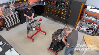
[Frankie] We are gonna get into the assembly process of our 632 and because we have it so far torn down we are definitely gonna go ahead and put new main and rod bearings in it. So the first thing we're gonna do is set up our main bearing clearance. A new set of Clevite main bearings are inserted into the cleaned main caps and the main saddles in the block that Pat just wiped down. The main caps and fasteners are prepped and installed just like they would be during assembly with CMD high pressure lube on the fasteners that are torqued to 100 pound feet. The caps are installed starting out the back to fit our dial bore gauge into the block. So we can use our SPI micrometer to measure the largest diameter of the rear main journal and set it to that size. Then we can use our micrometer to zero out our dial bore gauge to the journal size and take a direct vertical oil clearance measurement in the main bearings. The micrometer and dial bore gauge are individually set to each journal for accuracy and they are all measured between 24 and 26 ten thousandths. [Pat] Measuring the rod bearing clearance follows the same process starting by torquing the rod bearing cap to achieve the proper stretch of 73 to 77 ten thousandths on the ARP L-19 rod bolts. Then we can set the micrometer to the corresponding journal on the crank shaft, use it to zero our dial bore gauge, and take a direct oil clearance measurement for each rod, which are all set between 22 and 23 ten thousandths on this street application. Our Mahle Power Pack piston kit comes with a set of file fit rings that are 1.5-1.5-3 millimeter thick. So the next step is accurately setting the ring end gaps with our Summit Racing Pro Ring Filer. For this application naturally aspirated on pump gas the top ring gaps are set to 25 thousandths and the second rings are set to 28 thousandths. [Frankie] Once all the rings are fully cleaned we can assemble the Mahle pistons on the 6-700 long H-beam rods with copious amounts of Hot Shot's Secret Assembly Lube. The pistons have a 10cc effective dome, a phosphate coating over the whole piston, and an anti-scuff Grafal coating on the skirts. The 990 wrist pins are retained by a single sir clip on both sides, which can be installed with a pocket screwdriver. [Pat] Finally we can start putting parts into our large displacement big block. And after applying some assembly lube to the main bearings the 4.750 stroke crank can be dropped in with a new one piece rear main seal already installed. A crucial piece that cannot be missed on this Gen-6 big block is the O-ring that goes under the doweled number five main cap and seals the main oil feed passage way. Then each main cap can receive assembly lube and be installed in the correct position and orientation. They are tapped down with a rubber mallet. Then the main bolts can be torqued inside-out to 100 pound feet. [Frankie] When installing the piston rings we start at the bottom and work our way up. So with the support rail already installed we can put on the oil ring expander first and then the oil control rings by hand. Then the second ring and the top ring can be installed using this Goodson Ring Expander. This helps evenly apply pressure to the ring and prevents twisting or bending the ring trying to install them by hand. The rings also receive a decent amount of Total Seal Assembly Lube to help protect them during assembly and initial startup. [Pat] We like to install the cam shaft before the rods and pistons to make it easier to turn the engine over during the degreeing process. So the new bump stick gets installed next. It is a Comp Cams hydraulic roller that we had custom ground that has specs of 263 on the intake and 279 on the exhaust for durations at 50 thousandths lift. The lobes are set on a 110 degree lobe separation angle, and the lift at the valve with our rockers is 720 thousandths on both. We also had it ground with an LS firing order. So now it is 1-8-7-2-6-5-4-3. [Frankie] To reinstall the Jesel belt drive the rear thrust washer shim goes over the cam face and then the cam adapter can be bolted on with a small amount of silicone to prevent oil leaks. The front thrush shim can be lubed and installed before the O-ring sealed timing cover can be bolted on. Then the crank gear can be pressed on and the timing belt with the cam gear can be wiggled on with some patience. The cam bolt is left hand threaded and torqued to 70 pound feet with some thread locker. To set t-d-c number one on our degree wheel we'll just install the number one piston. Then we can check the intake centerline of the cam shaft, and for this application, a lower r-p-m street engine, we are advancing it six degrees to put the intake centerline at 104. [Pat] With that set the rest of the piston and rod assemblies can be installed using this ARP 4.600 bore fixed ring compressor and a Summit Racing Piston Installation Dead Blow. The rod caps are snugged down with an impact temporarily while we rotate the engine and install the other seven sets. Then the engine can be flipped upside down to final torque the rod bolts. The bolts are fully loosened for consistent torquing, and since we measured it earlier each rod can be torqued down to 95 pound feet to achieve the proper stretch. [Mike] Alright, there's the engine guys. What do y'all got going on today? [Pat] This is in short block form. It's coming really well. [Anthony] It's looking real nice. [Mike] We've got a project over there that we're just starting on. It's a 1989 Chevrolet truck, regular cab short bed but it's kinda slow with that old 350 small block. We need something to pep it up. [Pat] I think this is something that would make you very, very happy. [Mike] We want to play off that a little bit. Maybe go with a big block, LS. This one looks pretty good though. [Pat] You guys doing suspension? You doing tires and wheels? You doing everything? [Mike] Suspension, converting the transmission to a manual. [Anthony] Bigger brakes. [Mike] Make it a good, solid sport truck. [Frankie] We've got it to short block form. There's a lot of work left but pretty soon we'll be running it on the dyno. [Mike] When you get this thing on the dyno call us over and we'll come check it out. [Pat] We're gonna light it and then you can hear it and come running over. [Frankie] For now I think this is gonna be a great stopping point. Next time you'll see us wrap up this engine, get it on the dyno, and make some hot water. [Pat] If you want to see all other things that we do cool check out Powernation TV.
Show Full Transcript
[Pat] Today on Engine Power we are on the special projects unit where we cook up a 632 cubic inch big block Chevy to be big torque high tech pump gas tire killer. [Frankie] In today's show we're gonna start the transformation getting this engine prepped and into short block form with some high tech parts and a little bit of bling to get it ready for its new modern muscle truck home. ♪ ♪
♪ ♪ [ drill humming ] [Pat] Hey everyone, welcome to Engine Power. This is a brand new season, brand new episode, and a brand new engine build but the engine itself not so new. This engine has been kicking around our shop for a long time and has been in a couple of different configurations. From a race burning engine that makes well over 1,000 horsepower to a rot gut pump gas burning engine that is a good street bullet, but today it has finally found its final purpose. [Frankie] Today we are gonna take this big block Chevy, which is 632 cubic inches, and we're gonna put it in its final form. So this engine is 4.600 bore, 4.750 inch stroke. It's based on a Gen-6 big block Chevy block. But like Pat said, it has had several different parts run through it throughout the years and today we're gonna put even more parts in it and get it ready for its final life as a sweet street engine. So before we get started we're gonna show you how this engine started out, how many parts we've run through it, and then we'll get into what we're gonna do today. [ engine revving ] [Frankie] The first time you saw this engine it was being set up as a high horsepower mud truck bullet with over 15-to-1 static compression ratio and produced 1,022 horsepower and 821 pound feet with an r-p-m ceiling of 7,500. A BluePrint tall deck 4.600 bore big block Chevy engine block set the foundation and was filled with a 4,750 stroke forged crank. A set of H-beam 6.700 long rods and 42cc domed pistons rounded out the short block along with an aggressive solid roller bump stick driven by a Jesel timing belt drive. AFR 385cc aluminum heads topped it off and Jesel Sportsman 1.8-ratio rockers actuated the valves. An Edelbrock Super Victor-2 finished the induction with a Holley 4500 Sniper throttle body to make those big numbers on the dyno. [Pat] In the second version the engine was tamed down into a high torque street monster that could eat pump gas and blow the tires off of anything. The domed pistons were swapped out for a much lower compression 14cc dish for a 9.57-to-1 measured static compression ratio that would allow it to run on 93 octane. The cam shaft was also swapped for a smaller solid roller to lower the r-p-m range and put the red line at 6,500 r-p-m. All the other parts were refreshed and reused, and on the dyno it churned out 850 horsepower and 746 pound feet of torque. [Frankie] To make the changes we want for the final iteration of this power plant we're gonna be tearing it completely apart. Along the way we will be inspecting everything for an abnormal wear or potential failure points that need to be resolved. [Pat] Clean, one owner. [Frankie] After prying off the intake the valve train can be removed cylinder by cylinder with each one set at t-d-c compression stroke to remove any spring pressure before the rockers come off. All the valve train including the lifters is kept organized and in order for diagnosis and reassembly later on. The Jesel rocker stands do have to be removed to get access to the head stud nuts taking to care to keep the shims underneath orderly. [Pat] All of the head studs can be loosened from the outside in and removed from the block before pulling the cylinder heads to get the first look at the condition of the cylinders. Considering the abuse this thing has taken on the dyno they look excellent with minimal wear and a considerable amount of cross hatch still in the bore. Making our way to the bottom of the engine we can remove the electric water pump, crank trigger setup, and pull the harmonic damper off the crank snout. All of the ARP oil pan bolts can be removed and the oil pan gently tapped to break the seal and lower it down. [Frankie] After flipping the engine over we can remove the oil pump and then start removing the rod and piston assembly. We'll loosen the rod bolts on that crank throw, tap them with a rubber mallet to separate the rod and cap, and then we can remove the cap completely and gently push the rod down and out of the bores. With all eight assemblies removed we can loosen the left hand thread cam gear bolt, remove the timing set, and pull the crank gear off the snout with a steering wheel puller. After gently prying the timing cover off the cam shaft can be slid out. This one has specs of 274/284 at 50 and is set on a 114 degree lobe separation angle. It has a four-seven firing order swap and lift at the valve is 772 thousandths of an inch. It looks excellent and will be put on the shelf for a later build. Finally the half inch main bolts can be broke loose, zipped out, and the main caps carefully pried out of their registers so we can lift out the hefty 4.750 inch stroke crank. [Pat] Once again, things you look for. Underneath the cap make sure there's no fretting. When it's fretted like that that means it has gone into detonation, the caps are moving around probably because it was mis-tuned. Everything is nice on these, bearings look great. [Frankie] I would say for the health it's in it's really good. Probably gonna reuse a decent number of these, and then we'll just add all our new stuff. Up next, we get this engine refreshed and rebalanced to get this rebuild kicked off.
[Pat] The first thing we're gonna do is tell you about all the new parts we're using to reconfigure our 632 to its new duty as a street pump gas engine. First thing we're gonna do is actually gonna up the compression ratio. That sounds a little counterintuitive but let me explain. We had a 14cc effective dish on the piston. So we're gonna be raising it to a 10cc effective dome with this new Mahle PowerPak piston kit. Also we are going to go from a solid roller cam shaft to a hydraulic roller valve train. We had a new cam ground up by Comp with hydraulic roller lobes for our application and also we're putting a set of their Comp hydraulic roller lifters in. Plus we have to change the spring pressure in the heads. They're set up for a solid roller. So they have too much seat and open pressure. So we have a new set of springs from AFR to fit the bill but that is just half of it. [Frankie] The big upgrade on this engine is gonna be switching it to multi-port fuel injection and coil near plug ignition because that's what the guys want for the application that it's going in. To do that it's actually pretty easy because parts are readily available. It's all gonna be based around Holley's Terminator-X e-c-u. To get the manifold switched over we actually can get one right off the shelf. This is an Edelbrock Super Victor e-f-i manifold for a tall deck big block Chevy. We got the matching fuel rails and it has a 4500 flange on the top. So we have a Wilson Manifolds two inch bore 4500 flange throttle body with their IAC and TPS already on there. We have a set of 120 pound injectors so we can run any fuel we want. We have a set of Holley e-f-i Smart Coils for our coil near plug ignition, and to give the e-c-u everything it needs as far as timing for sequential fuel and ignition we have a 36 minus 1 big block Chevy crank trigger kit and an MSD billet cam sync because we don't need a distributor. So we just want to show you guys all the cool parts we're actually gonna be installing on this. Now we actually have to get back to work. ♪ ♪ [ drill humming ] [Pat] To prep the block itself we are going to quickly freshen up the bores with a 320 grit four and five-eighths inch flex hone making sure to use a sufficient amount of lubricant during the process. This will give us a fresh surface finish for our new rings to seal against and clean up any minor imperfections in the cylinder. Then we can remove all of the threaded oil gallery plugs and put the block in our JRI jet washer for a thorough cleaning. [Frankie] Now that we have our block prepped the next thing we're gonna do is balance the rotating assembly. Because we are changing the piston it's not too much different. It's about 16 grams difference between the old one and the new one, but we do want to rebalance the assembly to make sure that it is correct. I've gone ahead and got a bunch of the weights already and wrapping up now. We'll get some bob weights made, get them on our crank, and then do our first spin and see where we're at. The CWT software will automatically calculate the bob weight for you. So all we have to do is enter in the weight of each individual component. Then we can assemble and install a bob weight on each crank pin and get our first spin going. ♪ ♪ Not that bad. That's about what we thought it would be being such a slight difference between the two pistons. So we are 22 grams on the rear, 12 on the front, but as far as location the front is not bad. It's right on the edge of the counterweight but the back is gonna be a minor issue because for a moving weight you can't actually remove it from the counterweight side. It actually wants you to remove it from the rod journal side. So we're gonna have to figure out a way to add weight to the counterweight. Maybe fill in a few holes that are there and see how close that gets us. It probably will do it for us but we'll probably start there that way we can add material all at once and then remove material all at once. In order to add the small amount of weight needed for this job we will use the existing holes in the counterweights and fill them by welding them up. Using eighth inch ER-70-S filler material and even heat we can build up a few of the holes above the surface. [ grinder buzzing ] [Frankie] And then grind them down flush for a nice, smooth finish. This puts the heavy side of the imbalance back on the counterweight. So with a few smaller and well placed drill holes we can quickly bring the imbalance down within our target. Alright, we'll take that. That is .107 ounce inch on the front, .147 ounce inch on the rear. They are 184 degrees apart from each other. So they cancel out to .041 ounce inch on the center of the crank. We'll save that as our last spin and that's gonna work really good for this application. We didn't make a huge change because the pistons are very similar in size but it's still really important to have this done because if we look at the forces on the crank from before and after even just before if we had left it alone it would have been 178 pounds of force at 6,000 r-p-m. Now by actually balancing the crank we've minimized that down to nine and a half pounds of force. Huge, huge difference even though the pistons are very similar. So definitely something that needed to be done. Now it's finished up and we can move on. Coming up, our engine gets well read, well "red".
[Frankie] The next thing we want to do on our 632 big block Chevy is paint it but we can't do that yet because we need to modify our valve covers to mount our Holley EFI Smart Coils. Now the easiest way we found to do this is use Holley's coil relocation brackets. These are made so you can mount your coils anywhere inside the engine bay, but we can actually take them and weld them directly to our valve covers because they're made of aluminum. So what we're gonna do is get these prepped, get them centered where we like, and then we'll just weld them directly to them. [Pat] We don't need the mounting tabs on the coil brackets. So to get a cleaner look we can cut off the additional material using the band saw. With a flap disc we can nicely smooth out our cuts and remove the paint from the sections we will be welding on. After cleaning the bare aluminum with lacquer thinner to remove any contaminants we can locate the brackets where we want on the valve cover, clamp them down, and evenly tack them into place. After that it's just a matter of fully welding the bracket in several spots to provide support and now we have a clean and simple mounting solution for our 632's coil near plug ignition. The last thing we're gonna do before we assemble our engine is get it painted. We're gonna put some POR engine enamel on it and make it look great, but before we do that we have to get it cleaned up so we get good adhesion. So the first thing we are gonna do is clean all the parts we're painting with POR's Cleaner/Degreaser. What that's gonna do is make sure the surface is prepped properly and everything will stick to it. Gets all that grease and oil out, gives us a good surface. Then before we paint it we're gonna hit it with POR's Metal Prep. That promotes the adhesion of the paint. So all we've gotta do is get to cleaning. [Frankie] First we will spray down all the parts to remove any debris, and then we can start applying the cleaner/degreaser. [ water sloshing ] [Frankie] This is mixed with warm water in a four to one ratio, and we can use a stiff bristle brush to give the pieces a thorough scrubbing. We don't want any oils or grease that could ruin our paint job to be left on the surfaces. So we'll go over everything twice before giving it another rinse with the water hose. [Pat] The Metal Prep is used straight from the bottle and can be liberally applied with a brush to all the surfaces that will receive paint. To help protect the cylinder bores and bearing surfaces we heavily wiped them down with lubricant before we got started but it is still a good idea to be careful when applying the metal prep. Once everything has a wet coating on it we can let the etcher sit on the material for about 20 minutes before thoroughly rinsing it off with water. Then we can blow off the water with an air hose to prevent any rust from developing and push the parts inside to get them painted. [Frankie] The first thing we will be applying is POR-15's gray rust preventative coating, which will not only cover all the bare metal surfaces to protect them from corrosion but also acts as a base coat giving us a uniform color across all the parts so they match when our color is sprayed down. For this engine the color needed to be a bright, vibrant red and POR-15's Classic Ford Red fits that perfectly. After thinning it out a bit with their reducer we can load it into our h-v-l-p gun and give the parts a few solid coats for even coverage and a smooth, glossy finish. Stay tuned because up next we get our big red 632 ready for assembly and show you what it's going in.
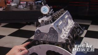
[Frankie] We are gonna get into the assembly process of our 632 and because we have it so far torn down we are definitely gonna go ahead and put new main and rod bearings in it. So the first thing we're gonna do is set up our main bearing clearance. A new set of Clevite main bearings are inserted into the cleaned main caps and the main saddles in the block that Pat just wiped down. The main caps and fasteners are prepped and installed just like they would be during assembly with CMD high pressure lube on the fasteners that are torqued to 100 pound feet. The caps are installed starting out the back to fit our dial bore gauge into the block. So we can use our SPI micrometer to measure the largest diameter of the rear main journal and set it to that size. Then we can use our micrometer to zero out our dial bore gauge to the journal size and take a direct vertical oil clearance measurement in the main bearings. The micrometer and dial bore gauge are individually set to each journal for accuracy and they are all measured between 24 and 26 ten thousandths. [Pat] Measuring the rod bearing clearance follows the same process starting by torquing the rod bearing cap to achieve the proper stretch of 73 to 77 ten thousandths on the ARP L-19 rod bolts. Then we can set the micrometer to the corresponding journal on the crank shaft, use it to zero our dial bore gauge, and take a direct oil clearance measurement for each rod, which are all set between 22 and 23 ten thousandths on this street application. Our Mahle Power Pack piston kit comes with a set of file fit rings that are 1.5-1.5-3 millimeter thick. So the next step is accurately setting the ring end gaps with our Summit Racing Pro Ring Filer. For this application naturally aspirated on pump gas the top ring gaps are set to 25 thousandths and the second rings are set to 28 thousandths. [Frankie] Once all the rings are fully cleaned we can assemble the Mahle pistons on the 6-700 long H-beam rods with copious amounts of Hot Shot's Secret Assembly Lube. The pistons have a 10cc effective dome, a phosphate coating over the whole piston, and an anti-scuff Grafal coating on the skirts. The 990 wrist pins are retained by a single sir clip on both sides, which can be installed with a pocket screwdriver. [Pat] Finally we can start putting parts into our large displacement big block. And after applying some assembly lube to the main bearings the 4.750 stroke crank can be dropped in with a new one piece rear main seal already installed. A crucial piece that cannot be missed on this Gen-6 big block is the O-ring that goes under the doweled number five main cap and seals the main oil feed passage way. Then each main cap can receive assembly lube and be installed in the correct position and orientation. They are tapped down with a rubber mallet. Then the main bolts can be torqued inside-out to 100 pound feet. [Frankie] When installing the piston rings we start at the bottom and work our way up. So with the support rail already installed we can put on the oil ring expander first and then the oil control rings by hand. Then the second ring and the top ring can be installed using this Goodson Ring Expander. This helps evenly apply pressure to the ring and prevents twisting or bending the ring trying to install them by hand. The rings also receive a decent amount of Total Seal Assembly Lube to help protect them during assembly and initial startup. [Pat] We like to install the cam shaft before the rods and pistons to make it easier to turn the engine over during the degreeing process. So the new bump stick gets installed next. It is a Comp Cams hydraulic roller that we had custom ground that has specs of 263 on the intake and 279 on the exhaust for durations at 50 thousandths lift. The lobes are set on a 110 degree lobe separation angle, and the lift at the valve with our rockers is 720 thousandths on both. We also had it ground with an LS firing order. So now it is 1-8-7-2-6-5-4-3. [Frankie] To reinstall the Jesel belt drive the rear thrust washer shim goes over the cam face and then the cam adapter can be bolted on with a small amount of silicone to prevent oil leaks. The front thrush shim can be lubed and installed before the O-ring sealed timing cover can be bolted on. Then the crank gear can be pressed on and the timing belt with the cam gear can be wiggled on with some patience. The cam bolt is left hand threaded and torqued to 70 pound feet with some thread locker. To set t-d-c number one on our degree wheel we'll just install the number one piston. Then we can check the intake centerline of the cam shaft, and for this application, a lower r-p-m street engine, we are advancing it six degrees to put the intake centerline at 104. [Pat] With that set the rest of the piston and rod assemblies can be installed using this ARP 4.600 bore fixed ring compressor and a Summit Racing Piston Installation Dead Blow. The rod caps are snugged down with an impact temporarily while we rotate the engine and install the other seven sets. Then the engine can be flipped upside down to final torque the rod bolts. The bolts are fully loosened for consistent torquing, and since we measured it earlier each rod can be torqued down to 95 pound feet to achieve the proper stretch. [Mike] Alright, there's the engine guys. What do y'all got going on today? [Pat] This is in short block form. It's coming really well. [Anthony] It's looking real nice. [Mike] We've got a project over there that we're just starting on. It's a 1989 Chevrolet truck, regular cab short bed but it's kinda slow with that old 350 small block. We need something to pep it up. [Pat] I think this is something that would make you very, very happy. [Mike] We want to play off that a little bit. Maybe go with a big block, LS. This one looks pretty good though. [Pat] You guys doing suspension? You doing tires and wheels? You doing everything? [Mike] Suspension, converting the transmission to a manual. [Anthony] Bigger brakes. [Mike] Make it a good, solid sport truck. [Frankie] We've got it to short block form. There's a lot of work left but pretty soon we'll be running it on the dyno. [Mike] When you get this thing on the dyno call us over and we'll come check it out. [Pat] We're gonna light it and then you can hear it and come running over. [Frankie] For now I think this is gonna be a great stopping point. Next time you'll see us wrap up this engine, get it on the dyno, and make some hot water. [Pat] If you want to see all other things that we do cool check out Powernation TV.
Engine Power Featured Projects
Engine Power Builds


Want more content like this?
Join the PowerNation Email NewsletterParts Used In This Episode
ARP
Rod Bolts
Comp Cams
Evolution Retro-Fit Hydraulic Roller Lifters
CWT Industries
Multi-Bal 5500
Edelbrock
Super Victor EFI Tall Deck Big Block Chevy Intake Manifold
Goodson Shop Supplies
Ring Expander
Holley
EFI Coil-Near-Plug Smart Coil Kit
Holley
EFI Crank Trigger System - BBC
Holley
Holley EFI Terminator X Service ECU
Holley
MSD Chevy BB Tall Block Cam Sync Plug
Holley
Smart Coil Remote Coil Relocation Brackets
Holley
Terminator X Fuel Injectors
Hot Shot's Secret
Adrenaline Assembly Lubricant
P.O.R. Products
POR15 Cleaner Degreaser
P.O.R. Products
POR15 Engine Enamel
P.O.R. Products
POR15 Metal Prep
P.O.R. Products
POR15 Rust Preventive Permanent Coating
Total Seal
Piston Ring Assembly Lube
WILSON MANIFOLDS
4500 Dominator Throttle Body