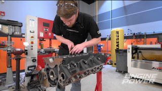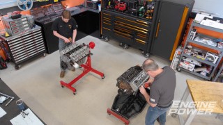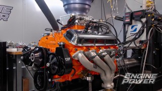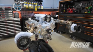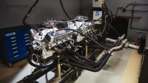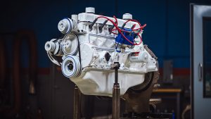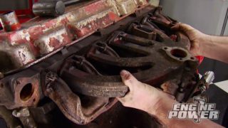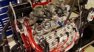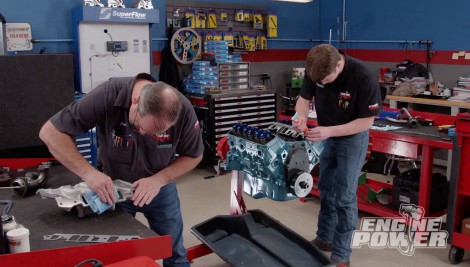
In-Depth Build Of An Old School Chevy 4.3L V6 Build Part 2
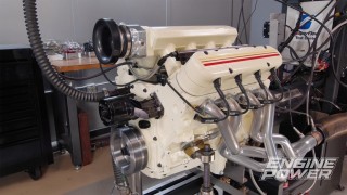
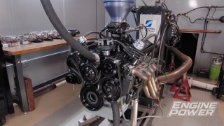
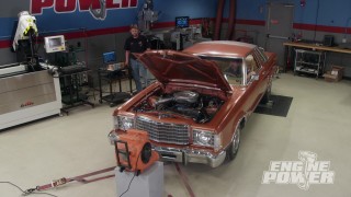
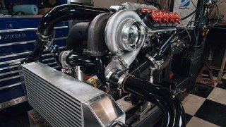
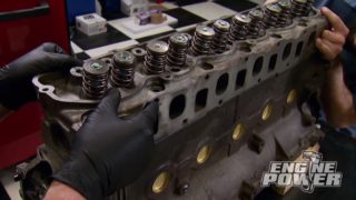
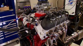
Once we install ported cylinder heads, upgraded valvetrain, and induction...the 4.3L engine shows what it can do in the dyno cell!
Season 9
Episode 2
Hosts: Pat Topolinski, Frankie Forman
First Air Date: January 24, 2022
Duration: 21 minutes 30 seconds