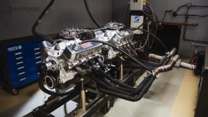
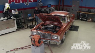
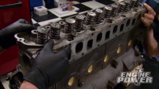
How Camshaft Timing Affects Engine Performance
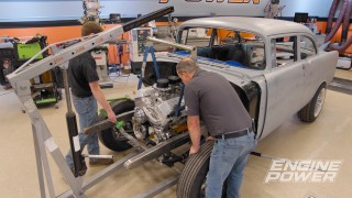
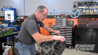
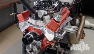
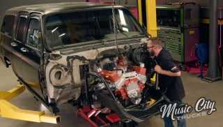
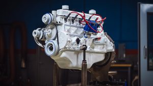
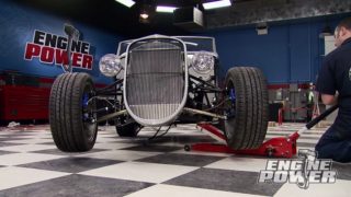
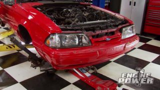
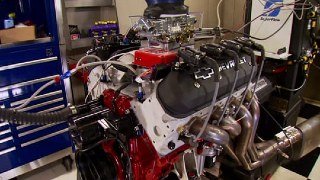
The first-generation Chevy Small Block deserves its reputation as a powerful and reliable engine. It’s the foundation for an old-school stroker build with an emphasis on durability.
Season 8
Episode 7
Hosts: Pat Topolinski, Frankie Forman
First Air Date: April 5, 2021
Duration: 21 minutes 35 seconds