Engine Power Featured Projects
Engine Power Builds


Want more content like this?
Join the PowerNation Email NewsletterParts Used In This Episode
Eagle Specialty Products
Eagle Forged H-Beam Rods
MAHLE Aftermarket
Elite Sportsman Drag Racing Pistons
Permatex
Ultra Slick
The Industrial Depot
Tools, Hardware, Shop Supplies
Episode Transcript
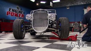
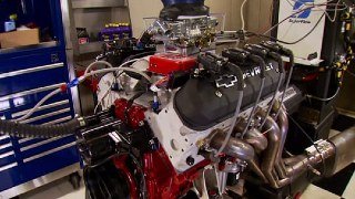
(Narrator)>> Today on Engine Power we're building a bullet that'll make more horsepower than any naturally aspirated engine we've ever had in the shop. When we're done with it this big block Chevy will power XOR's over the top Willys Wagon.
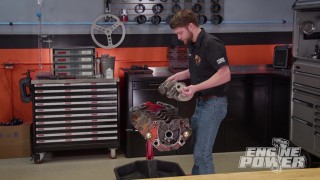
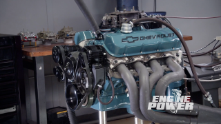
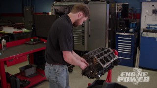
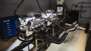
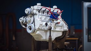
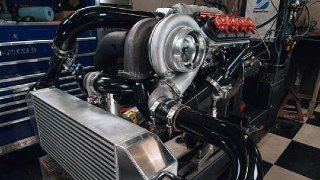
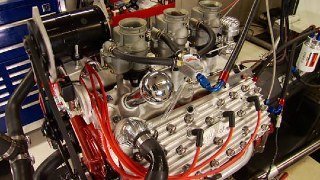
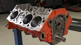
(Pat)>> Welcome to Engine Power. Today we are going to embark on an engine build that is a true race piece, and it will make more naturally aspirated horsepower than we have every made before. The more power you make the stronger the engine you need. So it's important to start with a solid foundation. This short block is the creation of Blueprint Engines, and it's made right here in the USA. It's a big block Chevy that's available in both standard and tall deck heights. Since we're looking for maximum displacement we opted for the tall deck. Another thing that will increase the displacement is the finished bore size of four-600, drastically larger than a stock big block Chevy. The included forged steel crank shaft has a stroke of four-750, which gives us 632 cubic inches. You have seen us run Blueprint engines in the past and it's for good reason. They're well designed, reliable, and they're perfect for someone who wants to save the time that it takes to spec out and build their own. Last year we helped build Factory Five's new '35 hot rod pickup, which was powered by the Blueprint 306 cubic inches small block Ford. It made 390 horsepower and 370 pound feet of torque. In keeping with the hot rod theme, triple Strombergs delivered the fuel. We fired it up, synced the carbs, and it ran like a top. ♪ ♪ Recently we beefed up a '74 Glencoe jet boat with a Blueprint 540 cubic inch big block Chevy. It pulled down 680 horsepower and 669 pound feet of torque in the dyno cell. [ engine revving ]
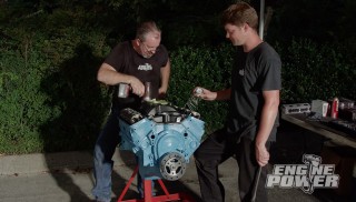
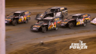
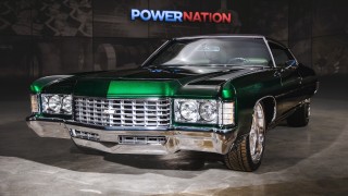
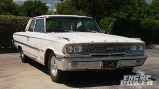
(Pat)>> Last week we spent the day at the lake and it was a face flapping, rooster tailing heck of a good time. We can't wait to get this boat back in the water, and we'll be bringing you more of that soon. This 632 cubic inch bullet is coming together for our friends down in XOR. Eliza and Jeremy are working on a classic piece of American off roading and it needs some stout horsepower. Let's go down and check it out. ♪ ♪ Hey what's going on down here?
(Eliza)>> Hey, what's going on?
(Pat)>> Well i came down to see what this engine is going in. Tell me a little bit about it.
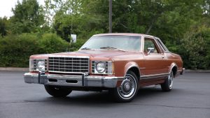
(Eliza)>> Well it's a 1963 Willys Wagon, and we want high horsepower to get through the mud. So we're going to custom four link, probably like 16 inches up. 46's, maybe 54's? Two and a half ton axles. So we're looking to get about 120 miles per hour wheel speed.
(Pat)>> Now I'm not familiar with these type of vehicles. Why does it need that kind of power for this application?
(Eliza)>> Well usually most of our vehicles have a lot of gearing. So they don't need a whole lot of horsepower, but since we want to have 120 miles per wheel speed to turn the mass of the tires we need high horsepower.
(Pat)>> Now this thing actually needed some power when it came in because it sounded, it sounded okay but I didn't see what was in it.
(Eliza)>> So it had a 305 in it. They had already swapped it out because originally these came with a four cylinder Hurricane engine. So maybe 100 horsepower?
(Pat)>> Maybe, it didn't sound bad. It definitely had the v-eight exhaust but it sounded a little on the anemic side.
(Eliza)>> A little bit, for what we're doing a little bit yeah.
(Pat)>> So say it made 100, 150 horsepower, it'll roughly have 10 times that now.
(Eliza)>> That would be wonderful.
(Pat)>> That's what we're shooting for. The engine's gonna be good. We're gonna crest 1,000 with this. This is gonna be the highest horsepower naturally aspirated engine we've done. And congratulations, you guys get to have it.
(Eliza)>> Thank you! We're excited that you're building us the engine.
(Pat)>> Now I might be stating the obvious but you don't see a lot of power adders like a blower or a turbo on these type of engines right?
(Eliza)>> No you don't. It's a little too sloppy out for that kind of setup. We don't want any kind of water or mud getting into the system. So that's why you don't see a lot of power adders. So that's why we need big cubic inches and a lot of horsepower.
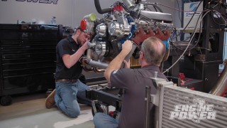
(Pat)>> Well I think we can help you out because the engine is going to make a lot of power, and if you don't mind would you come down and help a little bit? Maybe torque some stuff on?
(Eliza)>> Oh yeah, I'd love that.
(Pat)>> And you wouldn't want to run the dyno on something like that would you?
(Eliza)>> No I wouldn't!
(Pat)>> I didn't think so. So when it's ready we'll come down, let you throw the lever on it.
(Eliza)>> Awesome, I would love that!
(Pat)>> All right, well get back to work. I'm taking too much of your time.
(Eliza)>> Have a good one.
(Narrator)>> Up next, we crank up the compression on the big block.
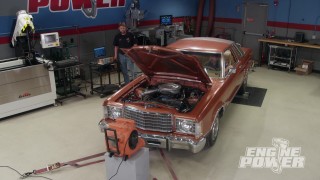
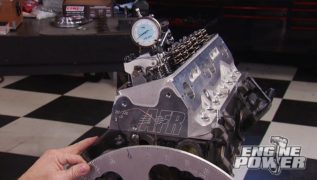
(Pat)>> We're continuing on the buildup of our 632 big block Chevy, and for the application down in XOR we're gonna have to make a bunch more power than this engine is currently setup to make, which means we're gonna have to change out a few parts. Right now it has a piston that will make 10.8 to one compression, which is friendly for pump gas but for what we're doing we're going to need a bunch more compression than that and here's how we're gonna get it. We'll be putting in a new set of Mahle Elite Sportsman drag series pistons. Now the big difference with these. These have a 42cc dome, which will increase our static compression ratio from 10.8 all the way up to 15.36 to one. Now these have hyper accurate ring lands and lateral gas porting to help improve ring seal, an zero-43, zero-43, three millimeter ring pack, wider pin bosses to help manage the increase inertial loads from these long stroke, high piston speed applications, and also come with an upgrade wrist pin that will withstand heavy nitrous use. All of Mahle's pistons come ready to run right out of the box with a properly sized wrist pin bore, a dry phosphate coating over the entire piston, and Mahle's patented Grafal anti-wear coating on the skirt. We're also changing up the connecting rod in this setup and I'll tell you why in a second. We'll be using a set of Eagle Specialties Forged H-beam rods. They're made out of 43-40 steel, have and HBeam design, and our setup for a nine-90 wrist pin. They are six-700 in length, and have been upgraded with an ARP L-19 rod bolt for high horsepower, high r-p-m applications. We needed the piston that we've chosen for the higher dome volume to get the compression ratio that we want for this application, but it won't work with the rod that came in this engine. That's why we're switching to the Eagle. Here is a quick look how we came up with the calculation of what we needed to use. What we are referring to is block height. The cylinder line of the crank shaft to where the cylinder head bolts on is called block height. In this case it is 10.200 inches. The piston's compression distance, plus the center to center length of the connecting rod, plus half the stroke, which is called crank arm, should equal the block height. We tailor the compression distance and rod length with our crank shaft to get that. So theoretically our piston is flat with the deck at t-d-c. In our case we have a stroke of 4.750 inches. Divide that by two and we have our crank arm, which is 2.375 inches. Add the connecting rod center to center distance, which is 6.700 inches as well as the 1.120 inches piston compression distance, and we have a total length of 10.195 inches. If our engine's deck height is truly 10.200 inches and we subtract the 10.195, we can determine that our piston is five thousandths of an inch in the hole. Of course we have to physically measure the deck height to see if that's correct. The first step is to put a rod and piston assembly together for mock up. ♪ After removing the current piston and rod combination we'll drop our mock up setup into place. ♪ ♪ [ drill spinning ]
(Pat)>> Then we'll run the piston up to top dead center, checking it with a dial indicator. Then we rock the piston back and forth finding the highest and lowest point in the bore at t-d-c. The average of those two measurements tells us how far the piston is in the hole. In our case it's eight and a half thousandths. This is one of the measurements that we do use to calculate final compression ratio for the combination, and this number also effects other things in the engine, but for right now we have this number and we can get the rest of the rods and pistons put together. When putting together our piston and rod assemblies we like to use Permatex Ultra Slick Engine Assembly Lube. This specially formulated lubricant protects components from excessive friction and wear during initial engine start up. ♪ ♪ Because the wrist pin's bore intersects the ring land on the oil ring we're gonna have to run a support rail, and it is held in place by this mark that keeps it from rotating. It supports the oil ring to keep it from burning excessive oil. ♪ ♪ We're using the Goodson power ring filer to gap the rings. This second compression ring is being gapped to 28 thousandths. A fine stone is used to deburr the edge. With the ring installed, a Summit adjustable ring squaring tool gets it perfectly into position, and a feeler gauge is used to check the gap. We're gonna be using an upgraded ring pack in this operation because of the amount of horsepower it's gonna make. It still has a standard tension oil ring to control the oil and a napier style second ring, which has a small hook on the edge that will actively scrape oil off the cylinder. The top is the special one. It is an uncoated steel nitrite ring, which will hold its tension better than a standard ductile ring.
(Narrator)>> Our quest for power continues with an aggressive cam and a heavy duty belt drive.
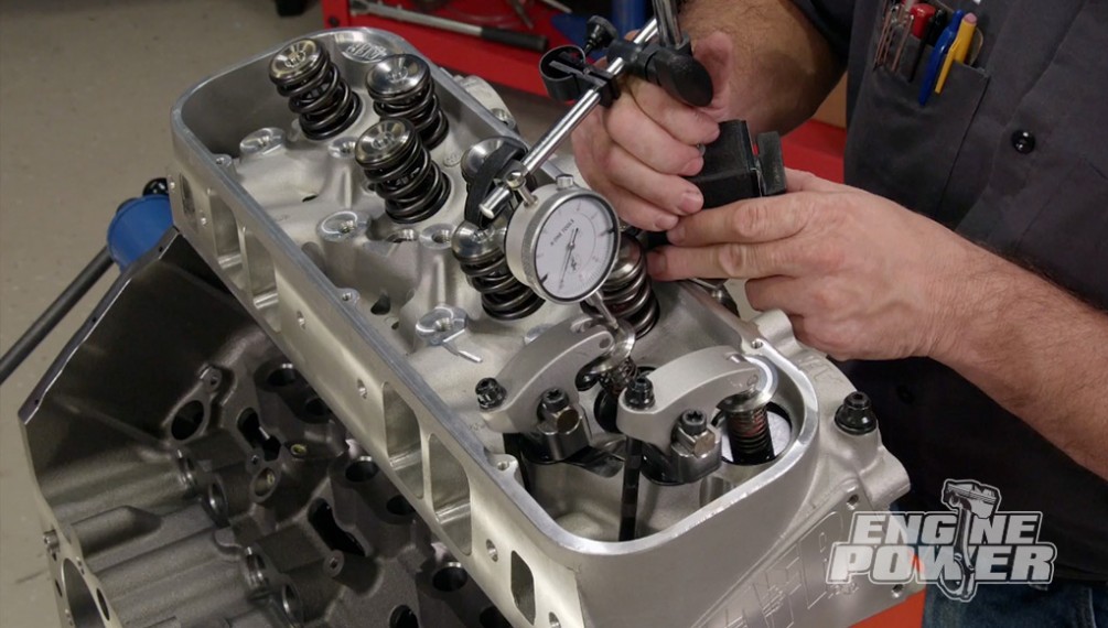
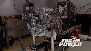
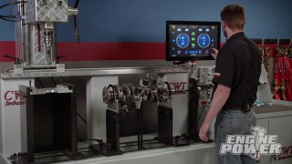
(Pat)>> Welcome back to Engine Power. We're building a 632 cubic inch Chevy big block that's gonna go into a '63 Willys Wagon down in the XOR shop. Once the pistons are in we can torque up the rods. The most accurate way to do this is using a rod bolt stretch gauge. This tool measures how much the bolt stretches under a specific torque load. The spec for this L-19 rod bolt is 73 to 77 ten thousandths. The goal is to tighten the fastener until it reaches its maximum clamping force without overtightening the bolt until it becomes distorted or compromised. In fact, whenever you're tightening a fastener to a torque spec what you're really doing is stretching the fastener to the ideal length under load, which on most fasteners is 75 percent of its yield. For the ultimate in accuracy and adjustment we're installing a Jesel belt drive system. It comes with a billet aluminum cover that's o-ringed for a leak proof seal. Next the cam shaft gently slides into the block. This is an off the shelf solid roller offering from Comp Cams. The specs are impressive by any standards. Duration at 50 thousandths lift on the intake is 285 degrees and 300 degrees on the exhaust. Lobe separation angle is 114 degrees. Gross valve lift on the intake side with a one point eight rocker is 873 thousandths, and 848 thousandths on the exhaust. The thrust washer gets installed on the cam shaft adapter provided by Jesel. Then it's wiped completely dry with lacquer thinner to remove any trace of oil. Next a thin but thorough layer of silicone covers the thrust shim before it's put in place. The cam shaft thrust plate slides in and is torqued to 96 pound inches, or eight pound feet. ♪ ♪ The crank gear is seated into place. Then the belt and the cam gear are installed and torqued to 70 pound feet. As always, we degree the cam shaft. This allows the engine to make the most power where we want it. The intake center line comes in at 113.5, which is a half degree advanced, and that is within a half degree of straight up, meaning the cam shaft's intake centerline is the same as its lobe separation angle. Now we don't plan on moving the cam around a lot because we want the engine to make power in a specific place in the r-p-m range. So we are gonna check our piston to valve clearance with the cam shaft in this position. Our solid roller lifters are from Comp Cam's premium sportsman series. Even though this is only mock up, we'll be certain the correct thickness head gasket. New gaskets will go on for final assembly. Once the head is set into place we'll drop in a few ARP studs to keep it there. ♪ ♪ We need to check for push rod length. So to do this we'll drop in a couple of adjustable push rods. We'll set the adjustor on our Jesel rocker arm to one full turn of adjustment. Then we'll lengthen the adjustable push rod while the cam is on base circle until we have the correct lash, which is 24 thousandths on the intake and 26 thousandths on the exhaust. ♪ ♪ We'll set up our dial indicator to check piston to valve clearance. The intake is checked at 10 degrees after t-d-c on split overlap. We zero out the indicator and press down until the valve contacts the piston. We have a roomy 100 thousandths clearance. We'll do the same for the exhaust valve but it's checked at 10 degrees before t-d-c on split overlap. The result, a whopping 135 thousandths. In other words this thing has a ton of clearance.
(Narrator)>> Up next, high flowing heads for our bullet.
(Pat)>> Now studs will help so you can align it.
(Pat)>> Welcome back and we're continuing on our 632 buildup, and next to go on is an ATI super damper we picked up from Summit Racing. Since everything is torqued up and ready to go, we'll install our Melling high volume oil pump and our new seven quart pan. To make the power we want to make we need a lot of air flow. So we called up Summit Racing and got a set of AFR 385cc rectangle Magnum 24 degree big block Chevy heads. Now there's nothing small about these. They have a two-350 intake valve, one-eight-eighty exhaust on a 121cc chamber. So they take a minimum of a four-250 bore. Now the 385 refers to the intake port size, which is 385cc. Now that will flow a massive 452 c-f-m at 800 lift. It also has a 135cc exhaust port, which flows at 344 c-f-m at that same lift. They are set up with a one-625 o-d spring, which is good for 850 lift, which is right in the range of our cam. These heads will make big power on a big engine. Because this bullet is going in the Willys project in XOR I thought it'd be a great idea to have Eliza and Jeremy down to help torque up the heads. ♪ ♪ All right, that one's for you. Now studs will help so you can align it. This on the bottom right there.
(Eliza)>> There it goes.
(Jeremy)>> Ooh, those are pretty!
(Pat)>> All right, studs are next. The reason we do studs first down here just for guide, and then later because we don't want to drag a head over a bunch of installed studs cause it'll drag some aluminum in.
(Eliza)>> Oh, and you're still letting us run the dyno on this right?
(Pat)>> Yes. If you get a little crazy on the dyno you can wound it. We'll keep you out of the woods.
(Jeremy)>> Just tell me what buttons to push.
(Pat)>> Tell me what buttons to push.
(Jeremy)>> That big lever, I'm just gonna push that forward.
(Pat)>> First click.
(Eliza)>> Okay! [ click click ]
(Jeremy)>> Makes you a little scarred sometimes when you've got to pull on them.
(Pat)>> Now once you've torqued several thousand of these you're gonna get used to it. I know it seems kind of complicated but it's not. You're just going in a circle.
(Jeremy)>> Do you always turn your torque wrenches back out?
(Pat)>> Absolutely, on a click type I always return it to zeroes.
(Jeremy)>> Perfect, well I'm gonna turn this one back out, and that gives us a point to also get out of here and let you finish putting this back in.
(Pat)>> I'll take that from you.
(Eliza)>> Take care of our baby!
(Pat)>> Nice job and I'll have you back down for the next part, which is probably gonna be on the dyno.
(Jeremy)>> Sounds great!
(Pat)>> Good job. For more information on anything you've see on today's show visit Powernation TV dot com. ♪ ♪ When building any engine one of the most important factors to consider is compression ratio. Now the parts that you choose for your build are designed to achieve a specific compression ratio but that is totally dependent on what you're doing. Now simply put, compression ratio is the maximum volume of the cylinder divided by the minimum volume of the cylinder. Or another way of putting it, the volume of the cylinder at b-d-c divided by the volume of the cylinder at t-d-c. And what makes compression ratio so important? It directly effects the power level and operating range of a given engine application. Generally speaking the higher the compression ratio of the engine the higher the potential power output. Higher octane fuels are required for most high compression engines to achieve optimum power output. Strictly speaking, static compression ratio measures a volume only, not pressure. There are high compression, low cylinder pressure engines that are designed primarily for fuel efficiency and not just out right power. In our world we want to generate as much cylinder pressure as possible to increase power. Higher static compression makes this easier to achieve. On the other end there are actually low static compression but high cylinder pressure engines that also require high octane fuel, but that involves something called dynamic compression ratio, and that's a topic we'll get into later on in depth. These engines are typically purpose built race bullets that have to conform to very specific compression rules but still make big power. There are five variables that effect compression ratio, and changing anyone of these factors will raise or lower it, and we're talking about volume. They are, number one, the swept volume of the cylinder. If you change the bore or stroke of a cylinder you will change the volume of that cylinder, and therefore it's compression ratio. Number two, combustion chamber size. Increasing it will lower the compression ratio and decreasing it will raise the compression ratio assuming that no other changes have been made. Number three, head gasket volume, meaning the gasket's bore size and the gasket's thickness. You might not realize it but the variations in head gasket volume can increase or decrease compression ratio by over a half a point. Number four, the volume of the cylinder at t-d-c with no other components. In most engines the piston stops just shy of being level with the deck of the engine block. This small volume of additional space lowers the static compression of the engine slightly. Number five, piston volume. A dome shaped piston takes away volume, increasing static compression. A disc shape piston adds volume, therefore decrease compression. Now you know the five factors that determine engine compression ratio. You can use this in order to more carefully plan your future engine builds. Next time we'll show you how to measure and calculate the static compression ratio in your project vehicle.
Show Full Transcript
(Pat)>> Welcome to Engine Power. Today we are going to embark on an engine build that is a true race piece, and it will make more naturally aspirated horsepower than we have every made before. The more power you make the stronger the engine you need. So it's important to start with a solid foundation. This short block is the creation of Blueprint Engines, and it's made right here in the USA. It's a big block Chevy that's available in both standard and tall deck heights. Since we're looking for maximum displacement we opted for the tall deck. Another thing that will increase the displacement is the finished bore size of four-600, drastically larger than a stock big block Chevy. The included forged steel crank shaft has a stroke of four-750, which gives us 632 cubic inches. You have seen us run Blueprint engines in the past and it's for good reason. They're well designed, reliable, and they're perfect for someone who wants to save the time that it takes to spec out and build their own. Last year we helped build Factory Five's new '35 hot rod pickup, which was powered by the Blueprint 306 cubic inches small block Ford. It made 390 horsepower and 370 pound feet of torque. In keeping with the hot rod theme, triple Strombergs delivered the fuel. We fired it up, synced the carbs, and it ran like a top. ♪ ♪ Recently we beefed up a '74 Glencoe jet boat with a Blueprint 540 cubic inch big block Chevy. It pulled down 680 horsepower and 669 pound feet of torque in the dyno cell. [ engine revving ]
(Pat)>> Last week we spent the day at the lake and it was a face flapping, rooster tailing heck of a good time. We can't wait to get this boat back in the water, and we'll be bringing you more of that soon. This 632 cubic inch bullet is coming together for our friends down in XOR. Eliza and Jeremy are working on a classic piece of American off roading and it needs some stout horsepower. Let's go down and check it out. ♪ ♪ Hey what's going on down here?
(Eliza)>> Hey, what's going on?
(Pat)>> Well i came down to see what this engine is going in. Tell me a little bit about it.
(Eliza)>> Well it's a 1963 Willys Wagon, and we want high horsepower to get through the mud. So we're going to custom four link, probably like 16 inches up. 46's, maybe 54's? Two and a half ton axles. So we're looking to get about 120 miles per hour wheel speed.
(Pat)>> Now I'm not familiar with these type of vehicles. Why does it need that kind of power for this application?
(Eliza)>> Well usually most of our vehicles have a lot of gearing. So they don't need a whole lot of horsepower, but since we want to have 120 miles per wheel speed to turn the mass of the tires we need high horsepower.
(Pat)>> Now this thing actually needed some power when it came in because it sounded, it sounded okay but I didn't see what was in it.
(Eliza)>> So it had a 305 in it. They had already swapped it out because originally these came with a four cylinder Hurricane engine. So maybe 100 horsepower?
(Pat)>> Maybe, it didn't sound bad. It definitely had the v-eight exhaust but it sounded a little on the anemic side.
(Eliza)>> A little bit, for what we're doing a little bit yeah.
(Pat)>> So say it made 100, 150 horsepower, it'll roughly have 10 times that now.
(Eliza)>> That would be wonderful.
(Pat)>> That's what we're shooting for. The engine's gonna be good. We're gonna crest 1,000 with this. This is gonna be the highest horsepower naturally aspirated engine we've done. And congratulations, you guys get to have it.
(Eliza)>> Thank you! We're excited that you're building us the engine.
(Pat)>> Now I might be stating the obvious but you don't see a lot of power adders like a blower or a turbo on these type of engines right?
(Eliza)>> No you don't. It's a little too sloppy out for that kind of setup. We don't want any kind of water or mud getting into the system. So that's why you don't see a lot of power adders. So that's why we need big cubic inches and a lot of horsepower.
(Pat)>> Well I think we can help you out because the engine is going to make a lot of power, and if you don't mind would you come down and help a little bit? Maybe torque some stuff on?
(Eliza)>> Oh yeah, I'd love that.
(Pat)>> And you wouldn't want to run the dyno on something like that would you?
(Eliza)>> No I wouldn't!
(Pat)>> I didn't think so. So when it's ready we'll come down, let you throw the lever on it.
(Eliza)>> Awesome, I would love that!
(Pat)>> All right, well get back to work. I'm taking too much of your time.
(Eliza)>> Have a good one.
(Narrator)>> Up next, we crank up the compression on the big block.
(Pat)>> We're continuing on the buildup of our 632 big block Chevy, and for the application down in XOR we're gonna have to make a bunch more power than this engine is currently setup to make, which means we're gonna have to change out a few parts. Right now it has a piston that will make 10.8 to one compression, which is friendly for pump gas but for what we're doing we're going to need a bunch more compression than that and here's how we're gonna get it. We'll be putting in a new set of Mahle Elite Sportsman drag series pistons. Now the big difference with these. These have a 42cc dome, which will increase our static compression ratio from 10.8 all the way up to 15.36 to one. Now these have hyper accurate ring lands and lateral gas porting to help improve ring seal, an zero-43, zero-43, three millimeter ring pack, wider pin bosses to help manage the increase inertial loads from these long stroke, high piston speed applications, and also come with an upgrade wrist pin that will withstand heavy nitrous use. All of Mahle's pistons come ready to run right out of the box with a properly sized wrist pin bore, a dry phosphate coating over the entire piston, and Mahle's patented Grafal anti-wear coating on the skirt. We're also changing up the connecting rod in this setup and I'll tell you why in a second. We'll be using a set of Eagle Specialties Forged H-beam rods. They're made out of 43-40 steel, have and HBeam design, and our setup for a nine-90 wrist pin. They are six-700 in length, and have been upgraded with an ARP L-19 rod bolt for high horsepower, high r-p-m applications. We needed the piston that we've chosen for the higher dome volume to get the compression ratio that we want for this application, but it won't work with the rod that came in this engine. That's why we're switching to the Eagle. Here is a quick look how we came up with the calculation of what we needed to use. What we are referring to is block height. The cylinder line of the crank shaft to where the cylinder head bolts on is called block height. In this case it is 10.200 inches. The piston's compression distance, plus the center to center length of the connecting rod, plus half the stroke, which is called crank arm, should equal the block height. We tailor the compression distance and rod length with our crank shaft to get that. So theoretically our piston is flat with the deck at t-d-c. In our case we have a stroke of 4.750 inches. Divide that by two and we have our crank arm, which is 2.375 inches. Add the connecting rod center to center distance, which is 6.700 inches as well as the 1.120 inches piston compression distance, and we have a total length of 10.195 inches. If our engine's deck height is truly 10.200 inches and we subtract the 10.195, we can determine that our piston is five thousandths of an inch in the hole. Of course we have to physically measure the deck height to see if that's correct. The first step is to put a rod and piston assembly together for mock up. ♪ After removing the current piston and rod combination we'll drop our mock up setup into place. ♪ ♪ [ drill spinning ]
(Pat)>> Then we'll run the piston up to top dead center, checking it with a dial indicator. Then we rock the piston back and forth finding the highest and lowest point in the bore at t-d-c. The average of those two measurements tells us how far the piston is in the hole. In our case it's eight and a half thousandths. This is one of the measurements that we do use to calculate final compression ratio for the combination, and this number also effects other things in the engine, but for right now we have this number and we can get the rest of the rods and pistons put together. When putting together our piston and rod assemblies we like to use Permatex Ultra Slick Engine Assembly Lube. This specially formulated lubricant protects components from excessive friction and wear during initial engine start up. ♪ ♪ Because the wrist pin's bore intersects the ring land on the oil ring we're gonna have to run a support rail, and it is held in place by this mark that keeps it from rotating. It supports the oil ring to keep it from burning excessive oil. ♪ ♪ We're using the Goodson power ring filer to gap the rings. This second compression ring is being gapped to 28 thousandths. A fine stone is used to deburr the edge. With the ring installed, a Summit adjustable ring squaring tool gets it perfectly into position, and a feeler gauge is used to check the gap. We're gonna be using an upgraded ring pack in this operation because of the amount of horsepower it's gonna make. It still has a standard tension oil ring to control the oil and a napier style second ring, which has a small hook on the edge that will actively scrape oil off the cylinder. The top is the special one. It is an uncoated steel nitrite ring, which will hold its tension better than a standard ductile ring.
(Narrator)>> Our quest for power continues with an aggressive cam and a heavy duty belt drive.
(Pat)>> Welcome back to Engine Power. We're building a 632 cubic inch Chevy big block that's gonna go into a '63 Willys Wagon down in the XOR shop. Once the pistons are in we can torque up the rods. The most accurate way to do this is using a rod bolt stretch gauge. This tool measures how much the bolt stretches under a specific torque load. The spec for this L-19 rod bolt is 73 to 77 ten thousandths. The goal is to tighten the fastener until it reaches its maximum clamping force without overtightening the bolt until it becomes distorted or compromised. In fact, whenever you're tightening a fastener to a torque spec what you're really doing is stretching the fastener to the ideal length under load, which on most fasteners is 75 percent of its yield. For the ultimate in accuracy and adjustment we're installing a Jesel belt drive system. It comes with a billet aluminum cover that's o-ringed for a leak proof seal. Next the cam shaft gently slides into the block. This is an off the shelf solid roller offering from Comp Cams. The specs are impressive by any standards. Duration at 50 thousandths lift on the intake is 285 degrees and 300 degrees on the exhaust. Lobe separation angle is 114 degrees. Gross valve lift on the intake side with a one point eight rocker is 873 thousandths, and 848 thousandths on the exhaust. The thrust washer gets installed on the cam shaft adapter provided by Jesel. Then it's wiped completely dry with lacquer thinner to remove any trace of oil. Next a thin but thorough layer of silicone covers the thrust shim before it's put in place. The cam shaft thrust plate slides in and is torqued to 96 pound inches, or eight pound feet. ♪ ♪ The crank gear is seated into place. Then the belt and the cam gear are installed and torqued to 70 pound feet. As always, we degree the cam shaft. This allows the engine to make the most power where we want it. The intake center line comes in at 113.5, which is a half degree advanced, and that is within a half degree of straight up, meaning the cam shaft's intake centerline is the same as its lobe separation angle. Now we don't plan on moving the cam around a lot because we want the engine to make power in a specific place in the r-p-m range. So we are gonna check our piston to valve clearance with the cam shaft in this position. Our solid roller lifters are from Comp Cam's premium sportsman series. Even though this is only mock up, we'll be certain the correct thickness head gasket. New gaskets will go on for final assembly. Once the head is set into place we'll drop in a few ARP studs to keep it there. ♪ ♪ We need to check for push rod length. So to do this we'll drop in a couple of adjustable push rods. We'll set the adjustor on our Jesel rocker arm to one full turn of adjustment. Then we'll lengthen the adjustable push rod while the cam is on base circle until we have the correct lash, which is 24 thousandths on the intake and 26 thousandths on the exhaust. ♪ ♪ We'll set up our dial indicator to check piston to valve clearance. The intake is checked at 10 degrees after t-d-c on split overlap. We zero out the indicator and press down until the valve contacts the piston. We have a roomy 100 thousandths clearance. We'll do the same for the exhaust valve but it's checked at 10 degrees before t-d-c on split overlap. The result, a whopping 135 thousandths. In other words this thing has a ton of clearance.
(Narrator)>> Up next, high flowing heads for our bullet.
(Pat)>> Now studs will help so you can align it.
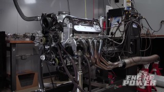
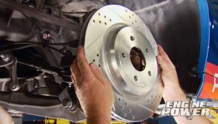
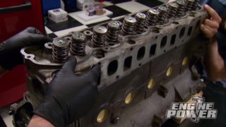
(Pat)>> Welcome back and we're continuing on our 632 buildup, and next to go on is an ATI super damper we picked up from Summit Racing. Since everything is torqued up and ready to go, we'll install our Melling high volume oil pump and our new seven quart pan. To make the power we want to make we need a lot of air flow. So we called up Summit Racing and got a set of AFR 385cc rectangle Magnum 24 degree big block Chevy heads. Now there's nothing small about these. They have a two-350 intake valve, one-eight-eighty exhaust on a 121cc chamber. So they take a minimum of a four-250 bore. Now the 385 refers to the intake port size, which is 385cc. Now that will flow a massive 452 c-f-m at 800 lift. It also has a 135cc exhaust port, which flows at 344 c-f-m at that same lift. They are set up with a one-625 o-d spring, which is good for 850 lift, which is right in the range of our cam. These heads will make big power on a big engine. Because this bullet is going in the Willys project in XOR I thought it'd be a great idea to have Eliza and Jeremy down to help torque up the heads. ♪ ♪ All right, that one's for you. Now studs will help so you can align it. This on the bottom right there.
(Eliza)>> There it goes.
(Jeremy)>> Ooh, those are pretty!
(Pat)>> All right, studs are next. The reason we do studs first down here just for guide, and then later because we don't want to drag a head over a bunch of installed studs cause it'll drag some aluminum in.
(Eliza)>> Oh, and you're still letting us run the dyno on this right?
(Pat)>> Yes. If you get a little crazy on the dyno you can wound it. We'll keep you out of the woods.
(Jeremy)>> Just tell me what buttons to push.
(Pat)>> Tell me what buttons to push.
(Jeremy)>> That big lever, I'm just gonna push that forward.
(Pat)>> First click.
(Eliza)>> Okay! [ click click ]
(Jeremy)>> Makes you a little scarred sometimes when you've got to pull on them.
(Pat)>> Now once you've torqued several thousand of these you're gonna get used to it. I know it seems kind of complicated but it's not. You're just going in a circle.
(Jeremy)>> Do you always turn your torque wrenches back out?
(Pat)>> Absolutely, on a click type I always return it to zeroes.
(Jeremy)>> Perfect, well I'm gonna turn this one back out, and that gives us a point to also get out of here and let you finish putting this back in.
(Pat)>> I'll take that from you.
(Eliza)>> Take care of our baby!
(Pat)>> Nice job and I'll have you back down for the next part, which is probably gonna be on the dyno.
(Jeremy)>> Sounds great!
(Pat)>> Good job. For more information on anything you've see on today's show visit Powernation TV dot com. ♪ ♪ When building any engine one of the most important factors to consider is compression ratio. Now the parts that you choose for your build are designed to achieve a specific compression ratio but that is totally dependent on what you're doing. Now simply put, compression ratio is the maximum volume of the cylinder divided by the minimum volume of the cylinder. Or another way of putting it, the volume of the cylinder at b-d-c divided by the volume of the cylinder at t-d-c. And what makes compression ratio so important? It directly effects the power level and operating range of a given engine application. Generally speaking the higher the compression ratio of the engine the higher the potential power output. Higher octane fuels are required for most high compression engines to achieve optimum power output. Strictly speaking, static compression ratio measures a volume only, not pressure. There are high compression, low cylinder pressure engines that are designed primarily for fuel efficiency and not just out right power. In our world we want to generate as much cylinder pressure as possible to increase power. Higher static compression makes this easier to achieve. On the other end there are actually low static compression but high cylinder pressure engines that also require high octane fuel, but that involves something called dynamic compression ratio, and that's a topic we'll get into later on in depth. These engines are typically purpose built race bullets that have to conform to very specific compression rules but still make big power. There are five variables that effect compression ratio, and changing anyone of these factors will raise or lower it, and we're talking about volume. They are, number one, the swept volume of the cylinder. If you change the bore or stroke of a cylinder you will change the volume of that cylinder, and therefore it's compression ratio. Number two, combustion chamber size. Increasing it will lower the compression ratio and decreasing it will raise the compression ratio assuming that no other changes have been made. Number three, head gasket volume, meaning the gasket's bore size and the gasket's thickness. You might not realize it but the variations in head gasket volume can increase or decrease compression ratio by over a half a point. Number four, the volume of the cylinder at t-d-c with no other components. In most engines the piston stops just shy of being level with the deck of the engine block. This small volume of additional space lowers the static compression of the engine slightly. Number five, piston volume. A dome shaped piston takes away volume, increasing static compression. A disc shape piston adds volume, therefore decrease compression. Now you know the five factors that determine engine compression ratio. You can use this in order to more carefully plan your future engine builds. Next time we'll show you how to measure and calculate the static compression ratio in your project vehicle.