Engine Power Featured Projects
Engine Power Builds


Want more content like this?
Join the PowerNation Email NewsletterParts Used In This Episode


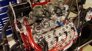
Aussiespeed
Aluminum Valve Cover
Aussiespeed
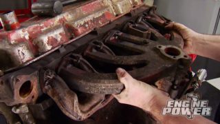
Dutra Dual Cast Slant 6 Headers
Aussiespeed
Hurricane Aussiespeed 4 Barrel Slant 6 Manifold
CWT Industries
CWT Multi-Bal 5500
Forney Industries
Forney 220 AC/DC Tig Welder
Gill Welding & Fabrication
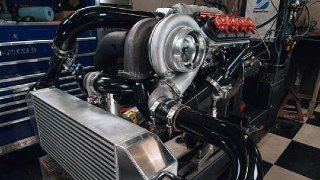
D-150 Slant 6 Turbo Header Pipe
Gill Welding & Fabrication
Slant 6 Intake EFI Conversion
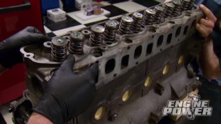
Goodson Shop Supplies
Goodson Valve Seat Grinding Stones
Molnar Technologies
Molnar Chrysler Slant 6 H-Beam Connecting Rods
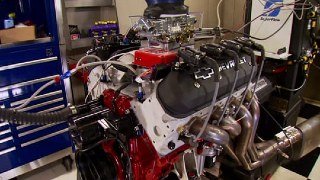
SuperFlow
SuperFlow SF-750 Flowbench
Wiseco Performance Products
Wiseco Custom Pistons
Yella Terra
Rocker Arms & Rocker Caps