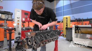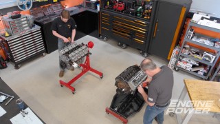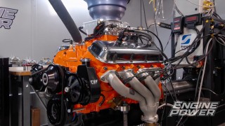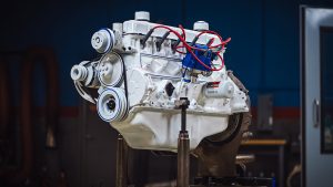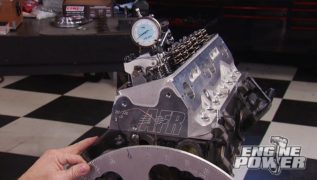
Boost-Ready Stroker LS3
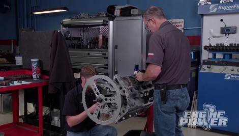
We’ve got big plans for this aluminum block! That includes stroking it to 419ci, along with a fully-forged rotating assembly that’s ready for a power adder!
Season 9
Episode 18
Hosts: Pat Topolinski, Frankie Forman
First Air Date: November 14, 2022
Duration: 21 minutes 30 seconds