
Engine Power Featured Projects
Engine Power Builds


Want more content like this?
Join the PowerNation Email NewsletterParts Used In This Episode
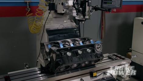
MSC
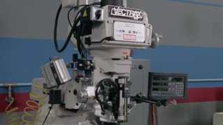
Vectrax - 10 Inch Wide x 54 Inch Long Table, Variable Speed Pulley Control, 3 Phase Knee Milling Machine with Digital Readout (DRO)
ARP
ARP is the Official Bolt Supplier to Engine Power
Matco Tools
MATCO Tools are the Official Tool Supplier to Engine Power