How To Install The Turbo In A 2nd Gen Swap
Mar 4th, 2019
Now that we’ve gotten the plumbing correctly installed for our 2nd Gen swap kit from Fleece Performance, it’s time to get to the good stuff!
The S467 turbo is going in under the hood of Truck Tech’s Ram and placement for both the turbo and manifold is crucial. On all Cummins-powered trucks from 2003 onward, the turbo was mounted on the back between the 4th and 5th cylinders which is a restrictive design. So swapping out a manifold where the turbo is mounted in the center of the engine will give you a more smooth, sweeping transition to allow for better exhaust pulses into the turbocharger. It also has a divided inlet for the turbine which provides quicker spooling of the turbo, lower exhaust gas temperatures and more power.
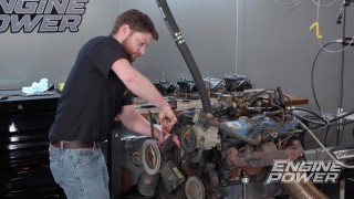
You can re-use your old hardware if you choose for this project. Will all the bolts in place, torque them to 35 ft.-lbs. working from the center, outward. With the exhaust manifold in place, next up is the turbo. The S400s are fairly heavy and awkward to handle so it can be easier to install it in pieces.
To get started, remove the V-band clamp and lift the compressor cover away. The same goes for the turbine housing. Then remove the cartridge and set it aside. Place a new gasket onto the manifold and slide the turbine housing over the studs onto the T4 clamps. A few nuts then hold it in place. Instead of the typical tapered gasket, Fleece provides a leak-proof O-ring fitting for the turbo drain. To get the cartridge installed, you want the oil feed on top and the drain on the bottom being as close to vertical as possible. The turbine and compressor wheel on a turbocharger are fairly delicate and easy to damage so if installed crooked, it could cause it to bind up and damages the turbo before even starting the truck.
To install without damaging, slowly and gently turn the compressor wheel back and forth as you slide the cartridge into the turbine housing. When it seats, it should spin freely so you know it’s not bound up. Connect the V-bands and you’re good to go.
Next, the oil drain line can be attached under the turbo and the insulated oil feed line can be installed. The powder coated compressor cover slides over the 67mm wheel and a larger V-band holds it in place. The passenger-side charge pipe slides in and is clamped into place with a V-band. The 4″ stainless downpipe slides from underneath the truck and connects to the turbine discharge with yet another V-band clamp making for quick removal if it ever needs servicing. Up front, the elbow for the air intake slides onto the compressor cover followed by the intake tube and filter finishing up the swap!
Want to read more articles like this?
Join the PowerNation Email NewsletterRead More from PowerNation